
Flywheel Bolt Circle: Measure PCD Before You Order
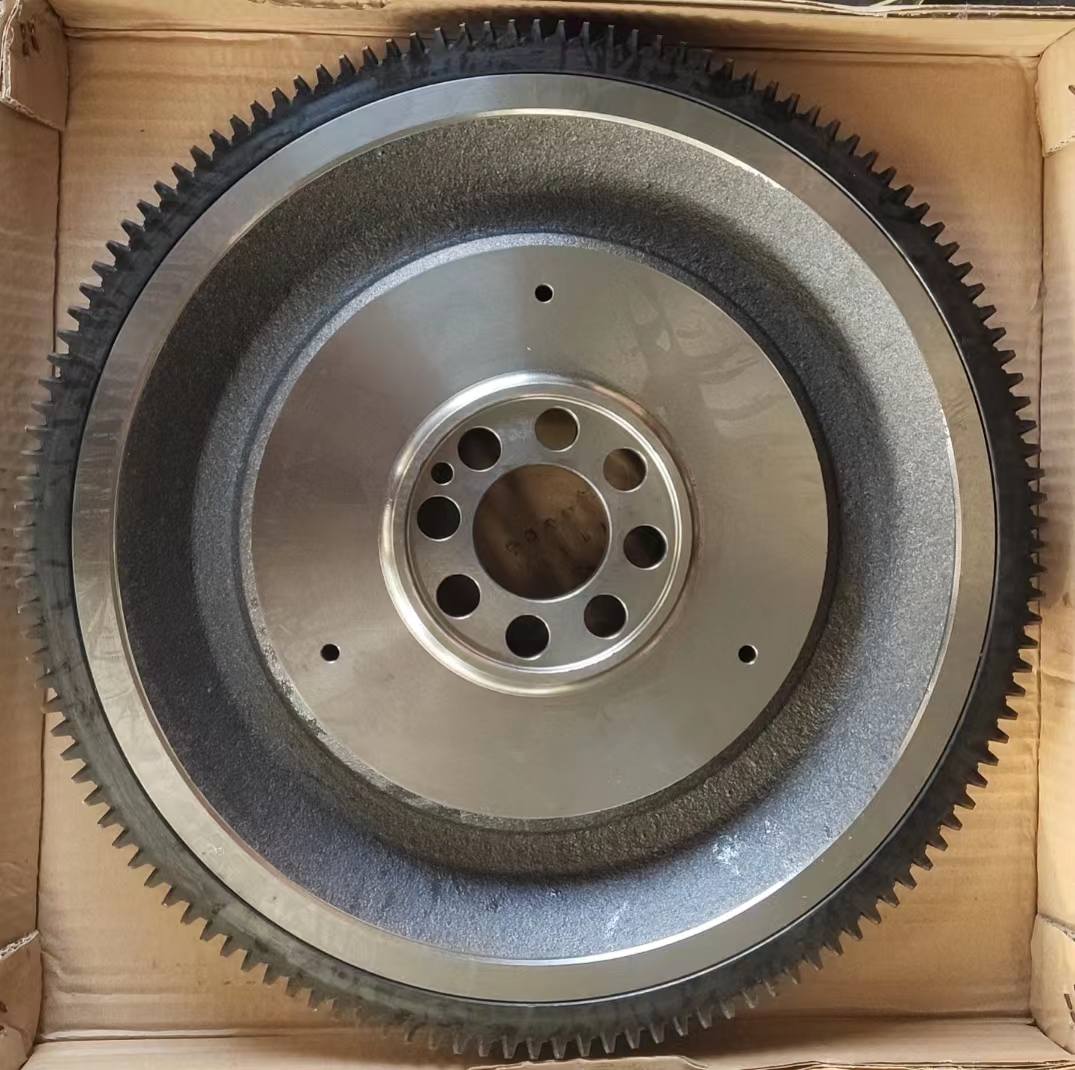
A flywheel has four machined features on one face. Buyers call all of them the bolt pattern. That is where fitment questions go wrong.
The flywheel bolt circle is not one circle. The holes that bolt the part to the crankshaft sit on one. The holes that carry the clutch cover sit on another. Between them is the pilot bore. Outside them is the ring gear.
Each one decides something different. A photo shows all four at once, which is why a photo alone rarely answers the question.
Table of Contents
- Three Circles and One Bore
- Same 350 mm Diameter, Six Holes or Eight
- The 430 mm Family Splits Eight and Ten
- One Hole More on the Same 153 Teeth
- How to Measure a Bolt Circle with a Caliper
- Four Numbers a Supplier Needs
- The Small Hole That Is Not on the Circle
- What a Photo Cannot Tell You
- When the Circle Matches and the Clutch Still Fits Wrong
- Frequently Asked Questions
- Send the Numbers and the Photo
Three Circles and One Bore
The fastest way to read a flywheel is from the centre out. Four features sit in a fixed order, and each one answers a different question.
| Feature | What you measure | What it decides |
|---|---|---|
| Pilot bore | Inside diameter at the centre | Gearbox input shaft and pilot bearing fit |
| Crankshaft bolt circle | Hole count, hole diameter, PCD | Whether the part bolts to your crank |
| Clutch cover circle | PCD, thread size, hole count | Which pressure plate bolts on |
| Ring gear | Tooth count, outside diameter | Starter mesh |
Most wrong orders start with the outside diameter. A part can be 430 mm across, carry 129 teeth, and still be wrong at the hub.
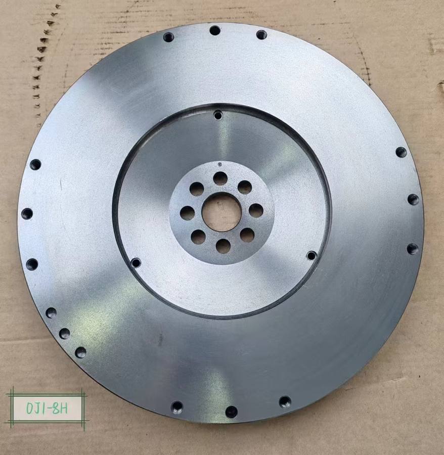
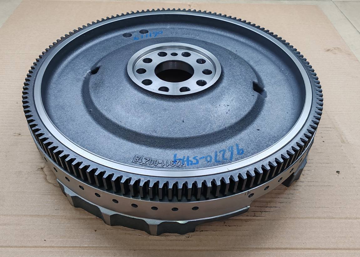
The photo above is the clearest example on our shelf. There is a small ring of holes at the hub, a middle ring, and a wide outer ring of holes near the rim. Three circles, one casting, three different jobs.
The Bore in the Middle
The pilot bore is the smallest feature and the easiest to overlook. Two supplier catalogues in our reference set list a 6205 bearing for the Isuzu 6BG1 and 6HE1 flywheels. A 6205 is 25 mm bore, 52 mm outside and 15 mm wide. Source level: supplier catalogue, single source.
That one line tells you the shaft size the part was built around. A flywheel that fits the crank bolts but not the input shaft will still go on, and then destroy the shaft.
Same 350 mm Diameter, Six Holes or Eight
This is the case that catches buyers most often. Two Isuzu flywheels, both 350 mm across, both 129 teeth, and not interchangeable.
| Engine | Size | Teeth | Crank holes | Reference |
|---|---|---|---|---|
| 6BD1 / 6BG1 | 350 mm | 129 | 6 | 1-12331164-3 |
| 6HE1 / 6HH1 | 350 mm | 129 | 8 | 8-94395450 |
Both rows come from supplier catalogues that agree with each other and with our own shelf. The 350 mm band in fact holds four different parts: 129 teeth with six holes, 129 teeth with eight holes, 140 teeth with six holes, and 140 teeth with eight holes.
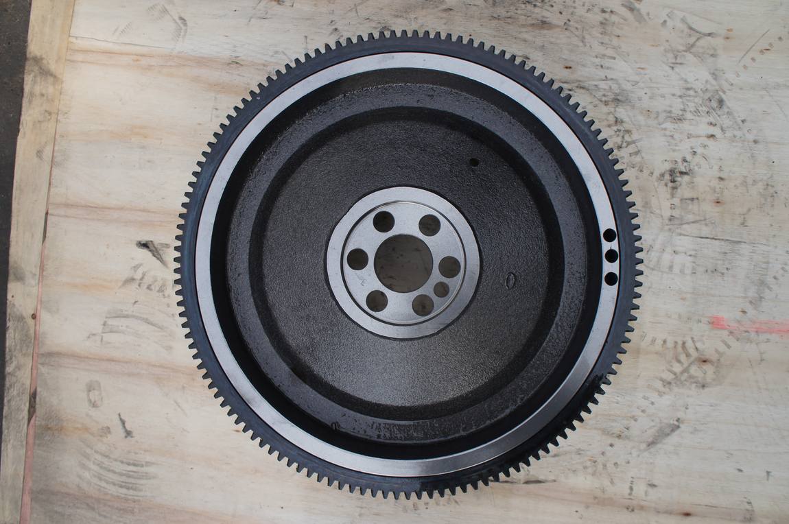
Put the two photos side by side. The ring gear is the same. The friction ring is the same. The only difference that matters is the number of holes in the machined hub, and one small hole sitting off that circle.
The 430 mm Family Splits Eight and Ten
The same split runs through the larger family.
| Engine | Size | Teeth | Crank holes |
|---|---|---|---|
| 6RA1 / 6RB1 | 430 mm | 139 | 8 |
| 6WA1TC / 6WF1 / 6WG1 / 6UZ1 | 430 mm | 139 | 10 |
Six engine models share one diameter and one tooth count. Only the hole count separates them. Our own 6WA1TC casting carries the ten-hole flange, which is how we settled a long-running catalogue conflict in favour of ten.
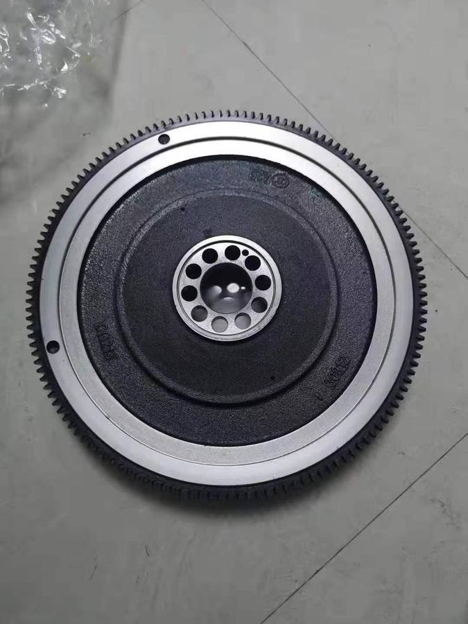
One Hole More on the Same 153 Teeth
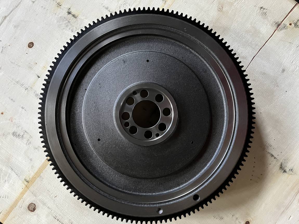
Our workshop holds two Nissan PE6T flywheels that differ by a single hole.
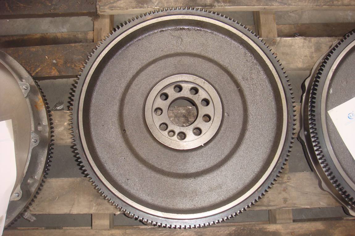
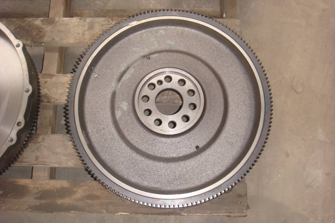
Both are 153 teeth. Both take a 430 mm clutch. The nine-hole version matches the published part number 12311-90228. The ten-hole version has no public number that we could confirm, so we sell it on measurement, not on a number.
That last sentence is the point of this article. When the catalogue stops, the caliper has to start.
How to Measure a Bolt Circle with a Caliper
You need one caliper, one part, and two minutes. There are two methods, and the easy one only works on an even hole count.
Measure Across Two Opposite Holes
On a six, eight, ten or twelve hole flange, pick two holes straight across the centre. Measure from the centre of one hole to the centre of the other. That reading is the pitch circle diameter, or PCD.
The hard part is finding the hole centres. A caliper reads edges, not centres. Two corrections handle it:
- Inside edge to inside edge: add one hole diameter.
- Outside edge to outside edge: subtract one hole diameter.
Measure Between Two Neighbouring Holes
On an odd hole count, or when the hub is too small to reach across, measure the gap between two adjacent holes and divide by a chord factor.
| Holes | Angle between holes | Multiply the chord by |
|---|---|---|
| 6 | 60 degrees | 2.000 |
| 8 | 45 degrees | 2.613 |
| 9 | 40 degrees | 2.924 |
| 10 | 36 degrees | 3.236 |
| 12 | 30 degrees | 3.864 |
The factors are one over the sine of half the step angle. The same numbers appear in every machinist handbook and in the online bolt circle calculators, so there is nothing proprietary about them.
Two worked examples from parts on our own shelf:
- The UD GE13 flywheel carries ten crank holes on a 107 mm circle. Adjacent hole centres therefore sit 33.1 mm apart.
- The Detroit MBE 900 carries eight clutch bolts on a 373.7 mm circle. Adjacent centres sit 143.0 mm apart.
Check the Circle Is Really a Circle
Measure one chord, then rotate the caliper 90 degrees and measure another. On a good part the two readings agree within a few hundredths of a millimetre.
If they do not agree, stop. Either the holes are not on one circle, or the hub is worn oval, or the part has been repaired. A bolt circle that is not a circle will bolt up and then shake.
Gauge pins give a cleaner reading than caliper jaws. Drop two pins into two holes and measure over the pins, then subtract one pin diameter. This is the method our inspection bench uses for first articles.
Four Numbers a Supplier Needs
Four numbers close almost every fitment question. Three real flywheels show why all four are needed.
| Flywheel | Outside diameter | Crank bolt circle | Pilot bore | Clutch side |
|---|---|---|---|---|
| UD GE13, 12311-00Z18 | 481 mm | 107 mm, 10 holes at 17 mm | 64.3 mm | 430 mm face, 131 teeth |
| Isuzu 6WG1 | 493 mm | 456 mm | 62 mm | 430 mm clutch, 40.3 kg |
| Detroit MBE 900 | 443 mm | clutch cover PCD 373.7 mm | not published | eight M14 bolts, ring gear seat 392.4 to 392.6 mm |
Evidence level: each row is a single published source, either a supplier specification page or a service manual. We have not cross-checked these three against a second document, and we say so rather than blending them into one average.
Read the third column against the fifth. A 430 mm clutch appears on a 481 mm flywheel and on a 493 mm flywheel. The clutch size does not identify the flywheel, and the flywheel diameter does not identify the clutch.
Why the Outside Diameter Is the Weakest Number
Buyers lead with the outside diameter because it is the easiest thing to measure with a tape. It is also the least useful of the four.
Two castings can share a diameter and differ at every functional face. Add a ring gear and the diameter grows again, because the teeth stand proud of the body. That is why the same part is quoted as 430 mm by one supplier and 487 mm by another, and both are describing a real dimension.
The bolt circle has no such ambiguity. It is machined, it is measured from hole centres, and it changes only when the part changes.
Watch the Hole Diameter, Not Only the Circle
A correct PCD with the wrong hole size is still a wrong order.
On the UD GE13 the ten crank holes are 17 mm across, which suits an M16 bolt. The Detroit MBE 900 clutch bolts are M14 by 1.5 mm, eight of them. Drop an M14 bolt into a 17 mm hole and the joint will clamp, then move.
Measure the hole with the caliper while you are already there. Ten seconds, and it removes a whole class of failures.
The Small Hole That Is Not on the Circle
Nearly every flywheel has one hole that does not belong to any circle. It is usually smaller, and it is usually offset.
Its job is to make the part go on one way only. Bolt holes are evenly spaced, so without that hole the flywheel could be fitted in several positions. The offset hole lines up with a dowel or a matching hole in the crank flange, and only one position works.
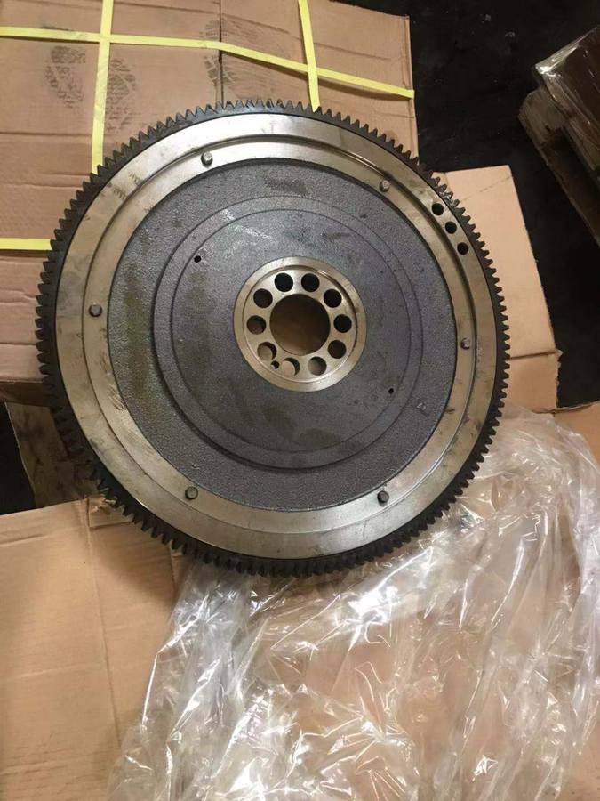
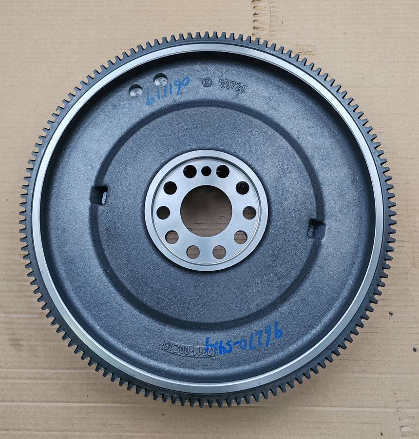
Look closely at the photo above. There is a ten-hole circle, one small hole below and left of it, and a second ring of six small holes further out. Those outer holes are not crank bolts. They locate something else on the clutch side.
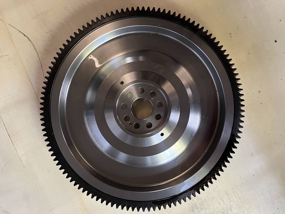
The Yuchai part above carries eight crank bolts and two small holes off the circle. We do not assume both are dowels. One may be a balance correction, drilled at the balancing station. That is exactly why we ask for a photo and a measurement instead of a description.
If the offset hole is oval, cracked, or drilled out, the part has a history. Treat it as a repair candidate, not a spare.
What a Photo Cannot Tell You
We take a lot of photos. They still cannot answer the main question.
- Counting holes from a photo fails when the small offset hole sits between two bolt holes. The eye adds it to the circle. The catalogue does not.
- PCD cannot be read from a photo without a scale in the frame. Two parts 50 mm apart in diameter look the same at different camera distances.
- Cast numbers are often unreadable. On several of our parts the number is a mould or batch code, not a part number at all.
- Primer, rust and grease fill the holes. A 17 mm hole painted twice reads 16 mm on a photo and looks smaller than it is.
- Our own workshop labels confuse the record. The green corner label on the first photo is our internal reference, not an OEM number, and it should never be quoted to a customer.
So we ask for two things: a photo taken square to the face, and four caliper readings. Together they settle in one email what a photo exchange settles in a week.
When a reading lands between two catalogue values, we say so. It is usually a worn part, a repaired hole, or a caliper held at an angle. We ask for a second reading before quoting, because a quotation built on a guessed circle is worse than no quotation.
When the Circle Matches and the Clutch Still Fits Wrong
A correct bolt circle is necessary, not sufficient. Once it matches, four more checks decide the order.
- Step height. The distance from the friction face to the bolt flange sets the clamp load. Machining the face changes it one to one.
- Clutch disc diameter. A 430 mm disc needs a 430 mm friction ring, not a 430 mm flywheel outside diameter.
- Release type. Push and pull covers use different heights and different bearing carriers.
- Ring gear teeth. One tooth changes the starter ratio and often the starter drive.
Two of those checks are covered in detail elsewhere on this site. Step height and machining limits are in flywheel resurfacing limits. Housing alignment and face runout are in flywheel housing runout.
Frequently Asked Questions
Is PCD the same as bolt circle diameter
Yes. Pitch circle diameter, bolt circle diameter and BCD all name the same circle, the one drawn through the hole centres. Some standards call the same dimension K.
Can you count the holes from my photo
Sometimes, and that is the problem. We will tell you what we see and then ask you to confirm the count on the part. A wrong count produces a wrong quotation, and the quotation is what the customer pays against.
Why do two flywheels with the same part number look different
Three common reasons: a revised casting, a different machining stage, or a supplier that grouped two variants under one number. We print what the part says and what the catalogue says, and we do not merge them.
Does the clutch diameter equal the flywheel diameter
No. A 430 mm clutch sits on flywheels from 481 mm to 493 mm in the examples above. Clutch diameter describes the disc, not the casting.
Is the pilot bearing always supplied with the flywheel
Not always. On the Sinotruk MC11 the two flywheel numbers differ mainly by the centre: 201-02301-6091 arrives with the bearing fitted in a recess, 201-02301-6085 arrives flat and bare. Same diameter, same ring gear, different centre.
What PCD tolerance do you hold
The drawing sets it, so we quote the drawing value rather than a house number. If you do not have the drawing, send the four readings and we will tell you what we can hold on that part.
Send the Numbers and the Photo
Send four numbers and one photo: outside diameter, crank bolt circle, hole count with hole diameter, and pilot bore. Add the clutch cover circle if you are matching a pressure plate.
We answer with the part number we can support, the drawing revision we are working to, and the points we still need to confirm. Nothing in that reply is guessed, and where a figure is single source we say so.
Browse the range on the product overview, check tooth counts against the ring gear and teeth guide, or send your readings to the quotation desk.
Related reading: the Isuzu flywheel part number chart, the Nissan and UD chart, and the UD GE13 page.