
Flywheel Timing Marks: TDC Line, Degree Scale, Date Code
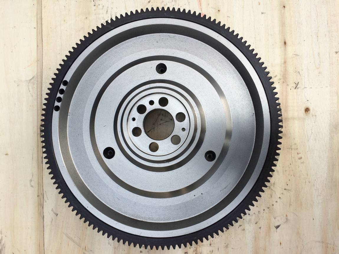
Table of Contents
- The Band Where the Marks Live
- The Zero Line and the Pointer
- Three Degree Marks on One ISUZU Rim
- A Graduated Scale on the Mitsubishi 8DC9
- Reading a Scale When the Numbers Are Gone
- The CH Code Is a Date, Not a Part Number
- What the Three Flywheels Actually Differ In
- What to Photograph Before You Order
- Evidence Behind This Article
- FAQ
The Band Where the Marks Live
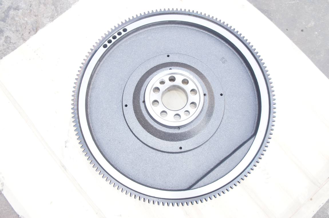
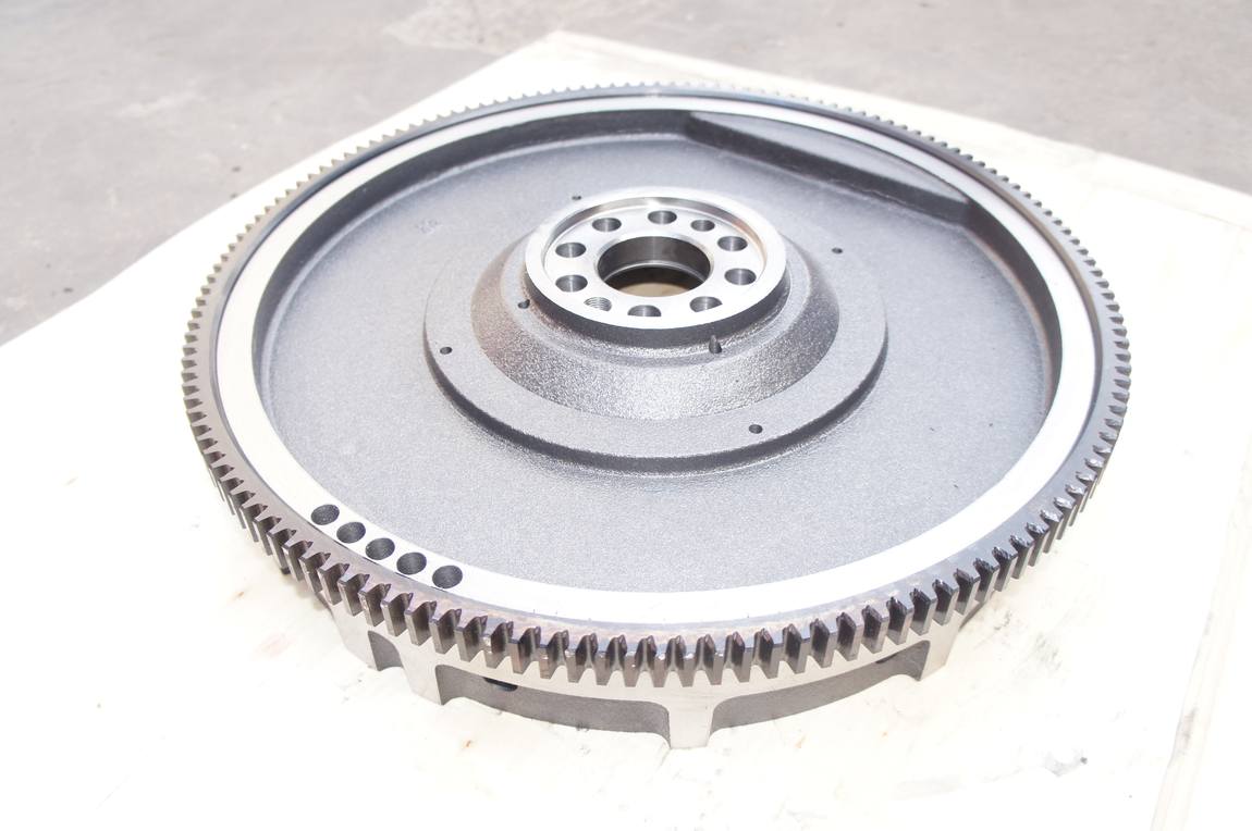
Take a flywheel off a pallet and look at it edge on. Between the starter ring gear and the friction face there is a narrow machined band, usually no wider than a thumb, running all the way around. On a painted casting it is the one strip that stays bare metal.
That band exists for a reason. It is turned true to the crankshaft bore, so an angular position marked on it is a real crank angle. That is why every timing reference a mechanic uses ends up there, and why the marks on it are cut after machining rather than cast in.
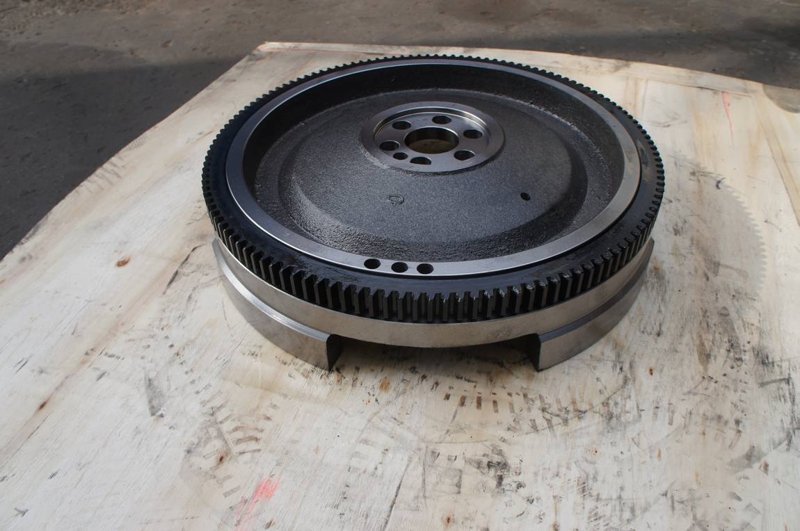
The same band is where most of the confusion in this article starts. Three different things get cut into it, they look similar at arm’s length, and only one of them is functional. Flywheel timing marks sit next to a maker’s code and a date, in the same shallow engraving, in the same few centimetres of steel.
The Zero Line and the Pointer
The first mark on the band is a long radial line, often with a small zero beside it. That line is the top dead centre reference for cylinder one. Bring it opposite the pointer and the piston is at the top of its stroke.
A mark on its own means nothing. It only works against a fixed pointer, and on most trucks that pointer sits on the flywheel housing, behind an inspection cover. A 1961 Land Rover owner’s manual describes the arrangement in plain words: timing is based on markings on the flywheel, visible next to a pointer under the inspection cover on the side of the flywheel housing, and the manual then lists what each line means, a TDC line, a 16 degree injection line and a valve lift line.
That is worth pausing on. The lines are not decoration and they are not a serial number. They are the interface between the engine and the person setting the injection pump.
Training material for diesel mechanics states the same thing from the other side: injection begins somewhere between 10 and 30 degrees before top dead centre, and that point is usually marked on the rim. The exact figure belongs to the engine, not to the flywheel in general.
Three Degree Marks on One ISUZU Rim
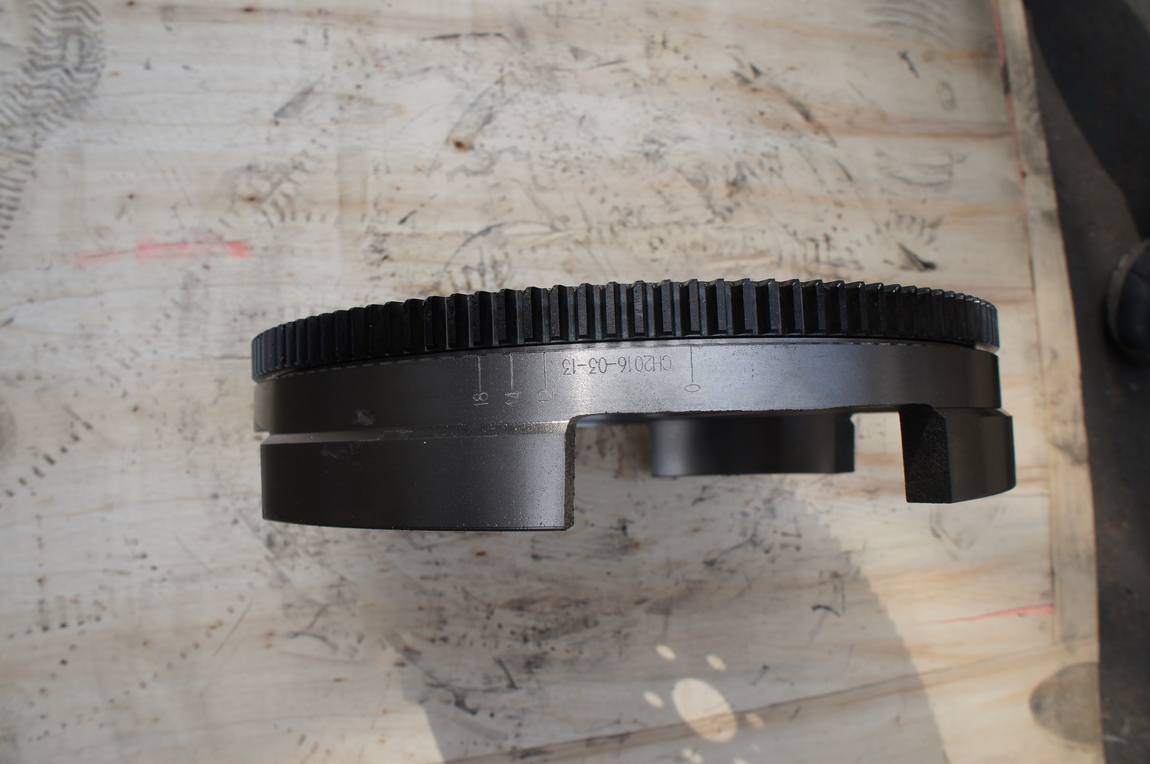
The ISUZU flywheel in our photographs carries more than a zero line. Along the band, in one continuous engraving, there is a zero line, a string reading CH2016-03-13, and then three further lines labelled 12, 14 and 18.
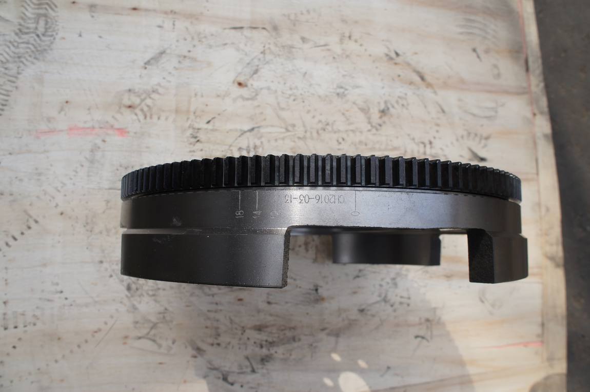
The three marks are not evenly spaced. The gap between 12 and 14 is visibly shorter than the gap between 14 and 18, which is what you would expect if the numbers are crank degrees and the lines are cut at true angular positions. That consistency is the only reason we are willing to read them as degrees at all.
Why one casting carries three settings
Why would one casting carry three settings? Because one casting serves several ratings. Published injection timing for the 6BG1 family is not a single number. The ISUZU workshop manual for the A-4BG1 series lists 12 degrees BTDC for the 6BG1 and 6BG1T, and 14 degrees for the 4BG1. A datasheet for the 6BG1-Z1 repower rating states 15 degrees BTDC. A manual for the A-6BG1QC industrial rating states an injection period of 14 degrees BTDC. All the published values we found land between 12 and 15 degrees.
That explains a 12 mark and a 14 mark on one part. It does not explain the 18.
What we will not claim about the 18
We are not going to invent a reason for it. Three possibilities are open, and we cannot separate them from a photograph. The 18 could belong to a rating we have not found a document for. It could be a different reference, such as a valve event rather than injection. Or the casting could serve an application where the flywheel, not the pulley, is the timing reference, and that application’s manual is the only place the scale is defined. Until we see that document, the honest statement is that 12 and 14 are consistent with published 6BG1 figures and 18 is unexplained.
The reference may be at the pulley, not the flywheel
There is a second reason for caution, and it is the one buyers rarely hear. The same ISUZU manual notes that the 6BG1 has eight timing notch lines punched on the crankshaft damper pulley, and that those notches are the ones to align. On a standard 6BG1 the degree reference is at the front of the engine, not at the flywheel. A 6BG1 flywheel with a full degree scale on the rim is therefore a build for a specific application, not the default. If your engine’s manual points at the pulley and your flywheel also carries marks, ask which reference the OEM intended before you trust either.
A Graduated Scale on the Mitsubishi 8DC9
The 8DC9 rim is a different animal. It does not carry three isolated marks. It carries a graduated scale: a 10, a run of fine ticks, a 20, and further along the band a 30. Ahead of the 10 there is a separate mark reading 14.
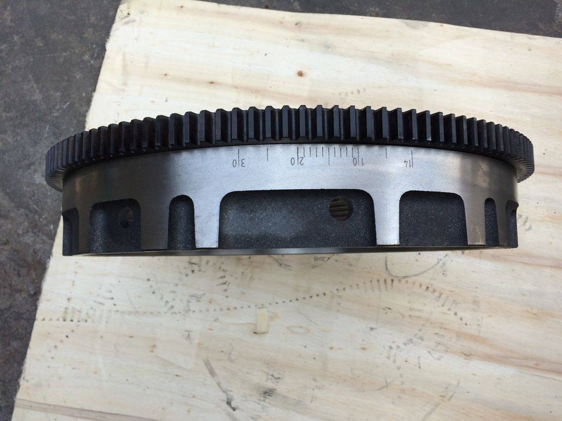
A scale like this is more useful than separate marks, because it lets a mechanic set a value the factory never printed. If the pump specification for a particular rating says 17 degrees, a scale with one degree ticks between 10 and 20 gets you there without arithmetic.
What we will not claim about the order
What we will not do is claim to have decoded the order. Read left to right along the band the numbers run 14, then 10, then 20, then 30, which is not an ascending sequence, and the band is curved so apparent spacing in a photograph is not angular spacing. We have not found a Mitsubishi service document that defines this exact scale, so we present the photograph and not an interpretation of it.
What rust takes first
What the photograph does establish is that the marks are engraved after machining, on the same band as the ring gear seat, and that they are shallow enough to disappear under a coat of paint or a skim of rust. That matters at the buying stage: a used flywheel whose band has been painted over has lost the only reference the mechanic had.
Reading a Scale When the Numbers Are Gone
Sooner or later the numbers are unreadable. The band is the first surface to rust, and a wire brush takes the engraving with it. There is a documented way through this, and it does not need a workshop manual for your exact engine.
The pitch method
A Yanmar service manual sets out the method for its TNV engines. The timing grid carries a TDC mark and marks at 10, 15 and 20 degrees BTDC, with the longer ticks 5 degrees apart. When you cannot tell which mark is which, you measure instead of reading. Measure the distance between two long marks, measure the distance from the TDC mark to the first long mark, and divide the second by the first. The result tells you how many 5 degree steps sit between TDC and that first mark, and the rest of the grid follows from there.
The ring gear as a ruler
The same logic works with the ring gear as your ruler. One tooth pitch is 360 divided by the tooth count, in crank degrees. A 129 tooth ring gear gives 2.79 degrees per tooth. A 136 tooth gear gives 2.65. Count teeth from the TDC line to the mark you care about, multiply, and you have an angle that does not depend on any number being legible.
Neither method replaces the manufacturer’s specification. Both of them stop you from guessing when the engraving has gone.
The CH Code Is a Date, Not a Part Number
Now the part that costs people money. Look again at the string on the ISUZU band: CH2016-03-13. It sits in the same engraving as the degree lines, at the same depth, in the same font. It looks exactly like an identifier, and it is one, but it is not a part number.
Two engines, two dates, one prefix
The HINO EF750 in the same photo set settles the question. Its band carries the same CH prefix and a date one week earlier, CH2016-03-07, and no part number at all.
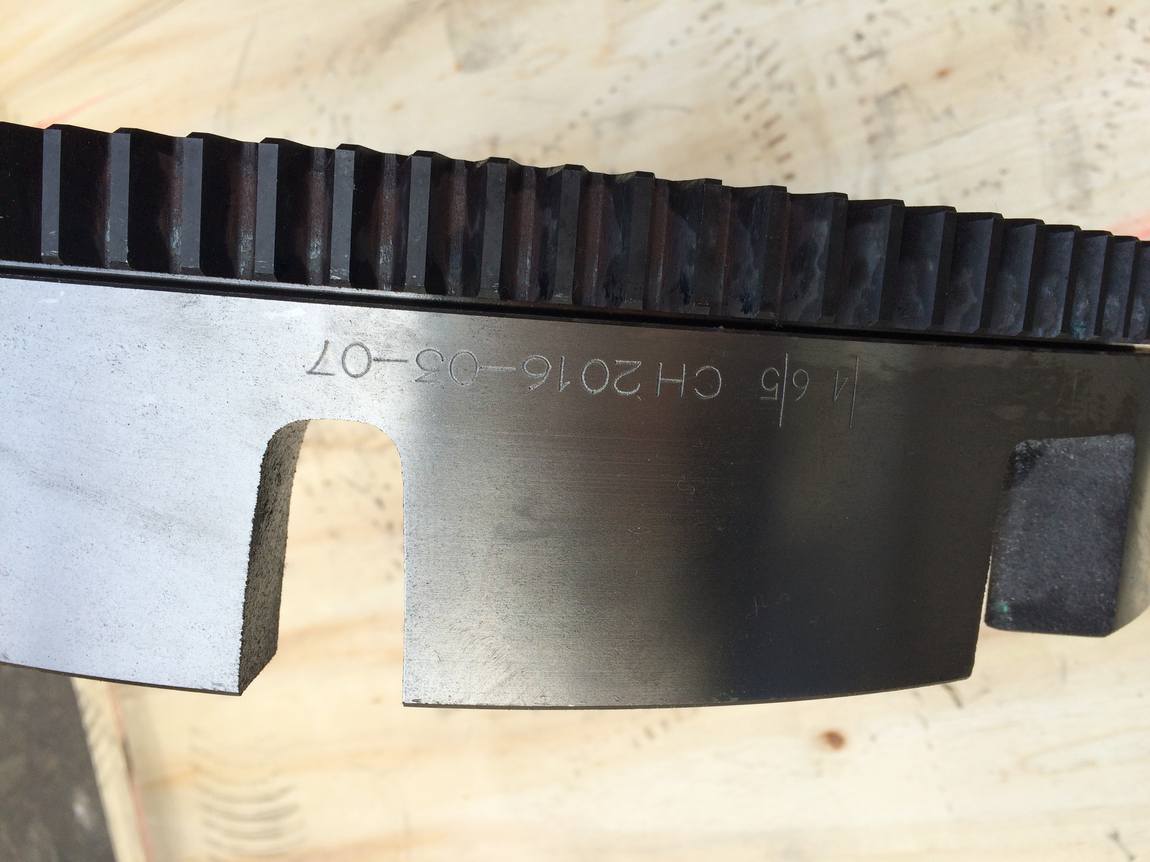
Two flywheels, two different engines, two makers’ castings, the same three character prefix and dates six days apart. Whatever CH denotes at the shop that applied it, it travels across parts and changes with the calendar. A part number does not behave like that. A date code does.
This is the same trap as the cast numbers on the face. On a DEUTZ flywheel we photographed last month, the raised numbers in the casting skin near the ring gear seat read as seven or eight digits that match nothing in the catalogue. Those are pattern and mould identifiers. The etch on the rim of these engines is one layer further out, and it is a trace code, not an identity.
The practical consequence
The consequence is short. If you quote CH2016-03-13 as a part number, no supplier will find it, because it is not a part number anywhere. Quote the engine, the measurements and a photograph of the band instead.
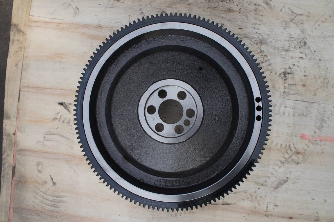
What the Three Flywheels Actually Differ In
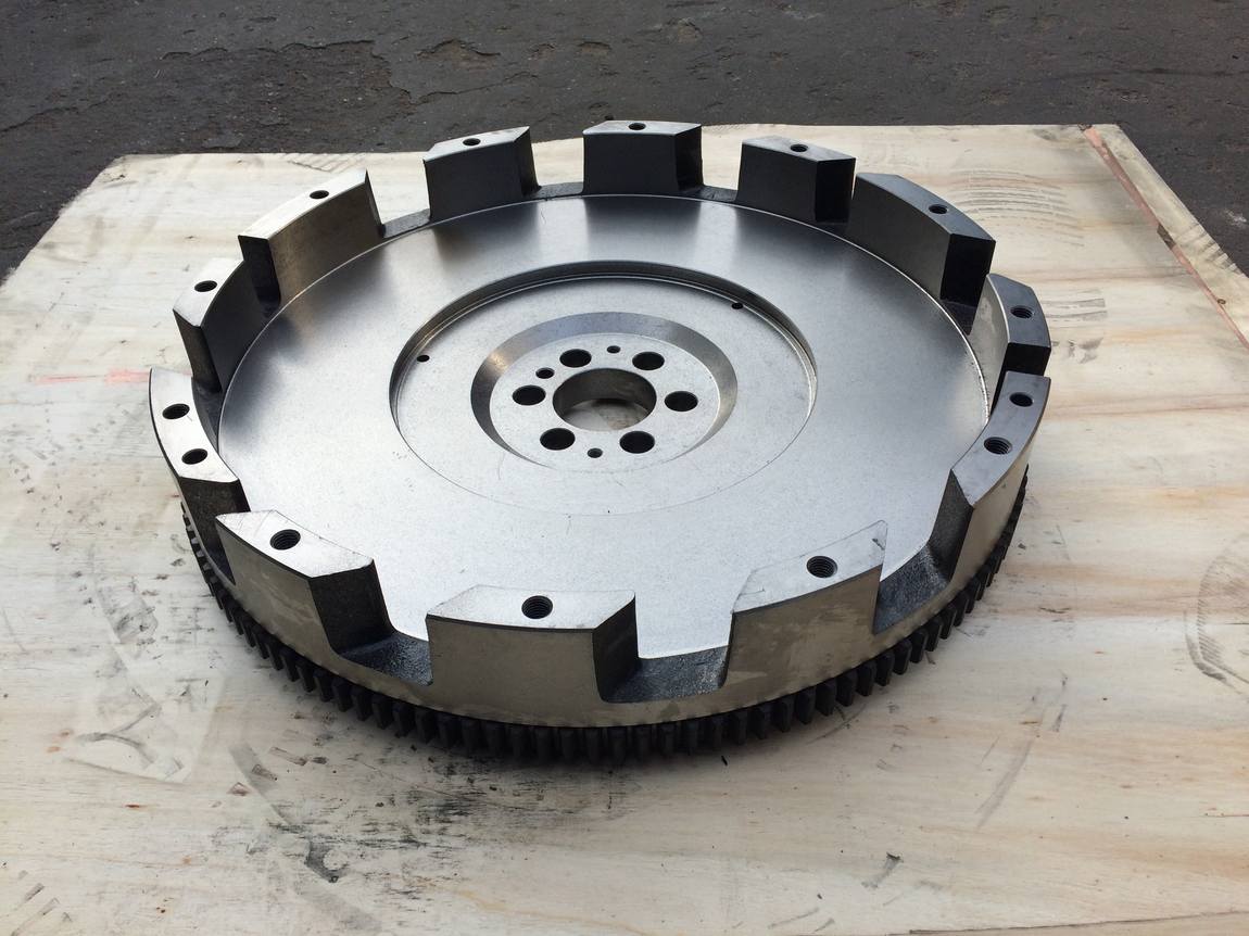
Three parts, photographed on the same pallet under the same light. Here is what the photographs support and what they do not.
| Engine code | Etched on the rim band | Read with confidence | Back face | Unconfirmed |
|---|---|---|---|---|
| ISUZU 6BG1 | Zero line, CH2016-03-13, marks at 12, 14 and 18 | Yes, all four elements legible at 3x | Four cast drive lugs in quarter segments | Meaning of the 18 mark |
| Mitsubishi 8DC9 | 14, then 10 with fine ticks to 20, then 30 | Numbers legible, order not decoded | Cast drive lugs, machined clutch face | Whether the ticks are 1 degree apart |
| HINO EF750 | CH2016-03-07 plus two short marks ahead of it | Date code clear, leading marks not clear | Cast drive lugs around the rim, fully machined face | Whether a degree scale exists elsewhere on the band |
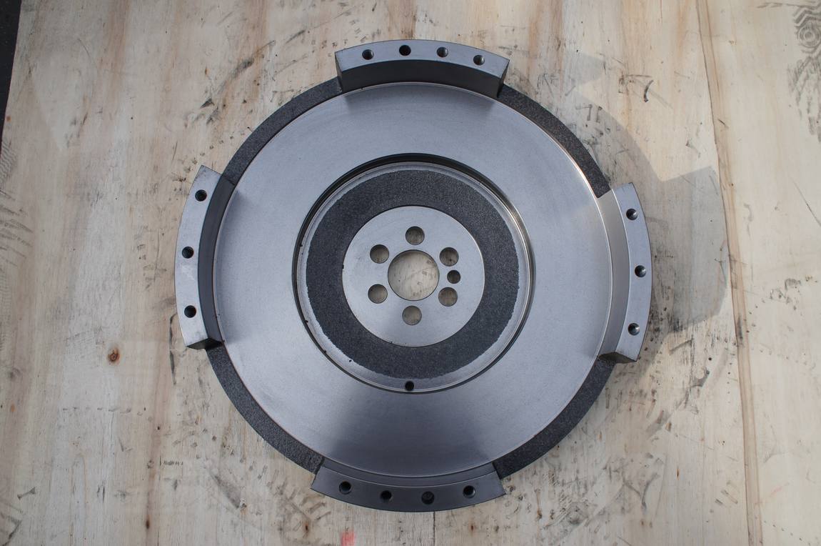
Two things are worth pulling out of that table. The first is that the legibility of the marks has nothing to do with the quality of the casting. All three are sound castings with clean machining. What differs is how much information the customer asked to have engraved.
The second is that none of the three carries a part number on the band. If you are identifying a flywheel from photographs alone, the band will tell you the timing reference and the production date. It will not tell you which part you are holding.
What to Photograph Before You Order
If the marks are the reason for your enquiry, photograph them properly. Four frames are enough.
The four frames
- The band, square on, with the whole engraved run in frame and the ring gear visible for context. Fill the frame with the band. A phone camera at ten centimetres beats a wide shot of the whole part.
- The same band with a steel rule laid alongside it. This is the only way anyone can turn a photograph into a measurement.
- The pointer, or the inspection cover it sits behind, on the housing.
- The engine plate, with the model and serial readable.
Add the hub bolt pattern and the ring gear outside diameter and you have covered almost everything a supplier needs. What you do not need is a photograph of the cast face: we will ask for the band anyway.
When the housing changes too
One warning about housings. If the pointer lives on the flywheel housing and you are replacing both the flywheel and the housing, the timing reference moves with the pair. A housing from a different rating can put the pointer a few degrees away from where the original sat. Send both parts, or send the housing part number with the flywheel photographs.
Evidence Behind This Article
| Claim | Where it comes from | Grade |
|---|---|---|
| Flywheel marks are read against a pointer under the flywheel housing inspection cover, and include a TDC line and an injection line | Land Rover Series IIA owner’s manual | Single source, primary document |
| Injection begins 10 to 30 degrees BTDC and is usually marked on the rim | Diesel mechanic training material, Mining Qualifications Authority | Single source, training document |
| Timing grid with TDC, 10, 15 and 20 degree marks; decode by measuring pitch between long marks | Yanmar TNV service manual | Single source, primary document |
| 6BG1 and 6BG1T at 12 degrees BTDC, 4BG1 at 14 degrees BTDC; 6BG1 has eight timing notches on the damper pulley | ISUZU A-4BG1 workshop manual | Single source, primary document |
| 6BG1-Z1 at 15 degrees BTDC | Engine datasheet for the repower rating | Single source |
| A-6BG1QC injection period 14 degrees BTDC | Equipment manual for the industrial rating | Single source |
| Zero line, CH2016-03-13 and marks at 12, 14, 18 on the 6BG1 sample | Our own photograph, taken in our shop | Primary evidence |
| CH2016-03-07 on the EF750 sample | Our own photograph, taken in our shop | Primary evidence |
| Graduated scale with 10, 20 and 30 on the 8DC9 sample | Our own photograph, taken in our shop | Primary evidence |
| CH is the customer’s own code, or a foundry’s code | No document found | Not used |
Everything in the table is either a document we can point at or a photograph we took. There is no fourth category in this article, and nothing has been inferred from a catalogue listing.
FAQ
Is the code etched on the rim the part number?
No. On all three flywheels in this article the etch is a maker’s code plus a date, and it changes with the production run rather than with the part. Part numbers on these engines live in catalogues and on the engine plate, not on the rim.
My flywheel has no marks at all. Can the engine still be timed?
Yes, by finding TDC another way, but it is a workshop job. The two common routes are reading the damper pulley, which is where ISUZU puts the 6BG1 notches, or finding TDC mechanically with a piston stop or a dial indicator on the piston crown, then marking the flywheel yourself against a fixed pointer.
The zero line does not line up with my pointer. What does that mean?
Three candidates, in order of likelihood. The housing is not the one the engine was built with, so the pointer has moved. The flywheel is from a different rating of the same engine family. Or the engine is being checked on the wrong stroke, since a four stroke engine reaches TDC twice per cycle and only one of them is the compression stroke.
Do you cut timing marks when you machine a flywheel?
Yes, when the drawing or the sample carries them. The marks are engraved after the band is turned, so they are cut to the drawing’s angular positions and not copied by eye. If your sample’s marks are worn away, send the drawing; if there is no drawing, we will ask for the engine model and the injection timing from your manual rather than guess.
Send the band photograph, the engine plate and the quantity to our quotation desk. If you are not sure which reference your engine uses, say so in the message and we will work it out from the manual with you.
Ring gear condition and replacement are covered on our ring gear page. Runout limits for the assembled flywheel are in our TIR measurement guide, and tooth counts by brand are in the ring gear teeth guide. For the ISUZU range as a whole, including the 6BG1, see our ISUZU flywheel part number chart.