
Flywheel Housing Runout: Bore and Face Alignment Limits
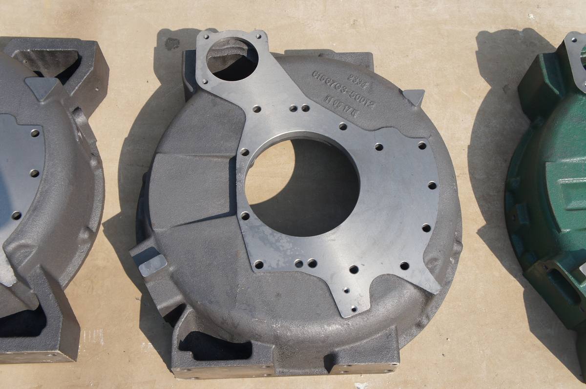
Table of Contents
- The clutch is rarely the part that failed
- Two measurements that fail in different ways
- What the standards actually allow
- Why two Cummins manuals print different numbers
- Set up before you trust a reading
- Bore runout in four points
- The pattern tells you shift or replace
- Face runout at the right radius
- Flywheel face runout scales with radius
- Housing bolt torque
- What a misaligned housing damages
- Causes that live on the housing
- What we machine and what we check
- Specifying a replacement housing
- Questions we get from workshops
A clutch that fails twice is not a clutch problem. The second disc wears on one side, the release drags, and the input shaft seal starts weeping a few months later. The gearbox goes back in, and the same complaint returns.
The flywheel housing is the reference for that whole train. Its machined bore centres the gearbox bell, and its machined face sets the angle of the gearbox flange. Both surfaces are cut relative to the crankshaft axis. Neither is checked often, because both stay hidden until the gearbox is out.
This article covers the two measurements, the published limits, and the pattern that tells a workshop whether to re-seat the housing or replace it.
The clutch is rarely the part that failed
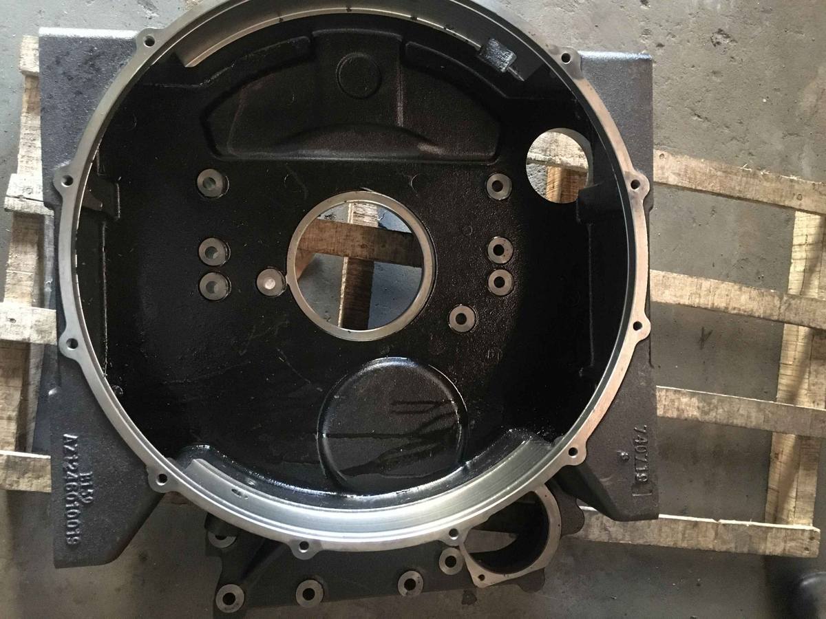
A clutch disc slides on the gearbox input shaft. It is centred between the flywheel face and the pressure plate. If the housing bore sits off the crankshaft axis, the input shaft is pushed sideways into the pilot bearing on every revolution.
The disc then runs slightly off centre. Wear becomes one sided. Release drags, because the disc cannot slide freely on a spline that is loaded sideways. The input shaft seal takes the same side load and leaks early.
A workshop that replaces the clutch and skips the housing check has replaced the symptom. The cause is still bolted to the back of the block.
Two measurements that fail in different ways
Bore runout is radial. A dial indicator rides on the inside of the machined pilot bore while the crankshaft turns. The reading shows how far that bore centre sits from the crank axis.
Face runout is axial. The indicator rides on the flat machined face that the gearbox flange bolts against. The reading shows how far that face leans away from square with the crank axis.
Both are reported as total indicator reading, or TIR. TIR is the difference between the highest and the lowest number seen in one full turn. It is not an average, and not a plus or minus figure.
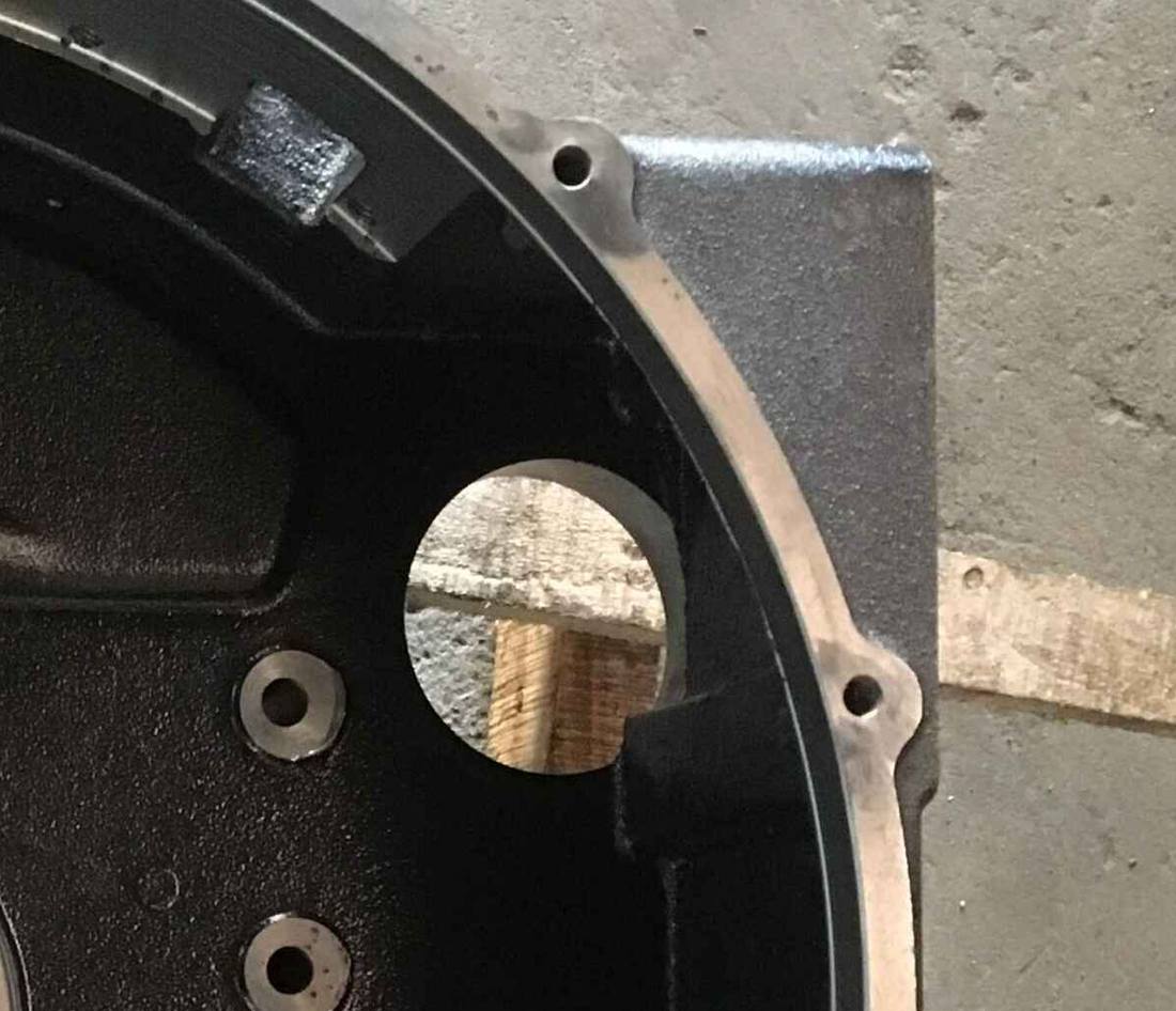
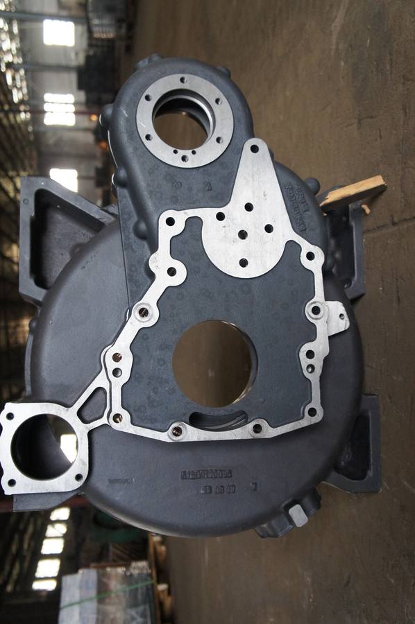
The bright ring with the bolt holes and the bore further in are the two surfaces being measured. Everything between them is as cast, and nothing there affects alignment.
What the standards actually allow
There is no single number for all engines. The housing size sets a base tolerance, and each engine maker then sets an in-service limit.
| Source | What is measured | Limit |
|---|---|---|
| SAE J617, by housing size | Pilot bore runout | SAE 6: 0.18 mm. SAE 5: 0.20 mm. SAE 4: 0.23 mm. SAE 3: 0.25 mm. SAE 2: 0.28 mm. SAE 00: 0.48 mm |
| Cummins ISX11.9 CM2250, 016-006 | Bore and face | SAE 00: 0.48 mm. SAE 0: 0.41 mm. SAE 1/2: 0.36 mm. SAE 1: 0.30 mm. SAE 2: 0.28 mm. SAE 3: 0.25 mm |
| Cummins N14, 016-006 | Bore runout | SAE 00: 0.30 mm. SAE 0: 0.25 mm. SAE 1/2: 0.25 mm. SAE 1: 0.20 mm. SAE 2: 0.20 mm. SAE 3: 0.20 mm |
| Detroit Series 60 and Series 50, 1.18 | Bore or face | 0.33 mm (0.013 in) for either |
| Detroit DD platform, bulletin 14 TL-7 | Bore or face | 0.30 mm (0.012 in) to be SAE compliant |
| Eaton installation guide | Housing pilot, SAE 1 and 2 | 0.20 mm (0.008 in) |
| Eaton installation guide | Flywheel pilot bore | 0.127 mm (0.005 in) |
| Eaton installation guide | Clutch housing face and pilot | 0.076 mm (0.003 in) |
Two notes on that table. The SAE J617 rows come from a published summary of the standard, not from the paid document. Treat them as the shape of the requirement, not a replacement for it. The SAE 1 row is blank in that source because the summary did not list it.
The size names run the opposite way to the numbers. SAE 2 is a 447.68 mm pilot bore, SAE 1 is 511.18 mm, and SAE 00 is larger still. Bigger bore, more allowed runout: the same angular error produces a larger arc as the radius grows.
Why two Cummins manuals print different numbers
The ISX11.9 table and the N14 table come from procedures with the same number, 016-006. Their limits differ by up to 0.10 mm for the same housing size. Both are Cummins documents.
The ISX figures line up with the SAE J617 tolerances almost exactly: 0.48, 0.28 and 0.25 mm appear in both. The N14 figures are tighter across the range: 0.30 mm where the standard allows 0.48 mm.
That is not a contradiction to resolve. It is two policies for two engine generations. A 2020 engine and a 1995 engine do not share a wear allowance, even when they share a housing size. Use the manual for the engine in front of you, and do not carry a number across.
Set up before you trust a reading
Three things can spoil a runout reading before the gauge even moves.
Crankshaft end play is the first. If the crank can slide in and out, the indicator records that movement as face runout. Eaton’s guide says to check end play against the maker’s limit first, and to stop if it is excessive. Cummins and Detroit solve it the same way during measurement: push the crankshaft fully toward the front of the engine at every measuring point.
Rotation is the second. Turn the engine by hand or with a barring tool. Eaton states plainly that the engine must not be cranked on the starter. Detroit adds a detail: remove the wrench or barring bar before reading the dial, because the weight of the tool distorts the number.
The indicator mounting is the third. The arm must be rigid. A bar that sags under its own weight gives a reading that looks stable and is wrong. Cummins mounts the gauge on the crankshaft through an adapter, and accepts any method only if the arm cannot sag.
Cleanliness comes before all three. Detroit’s procedure is blunt: if runout is out of limit, remove the flywheel and housing and look for dirt or foreign material between the housing and the block or oil pan. Paint overspray, gasket residue and blasting grit all sit in that joint. A chip of paint 0.2 mm thick tilts the housing further than the tolerance allows.
Bore runout in four points
The method below follows the Cummins and Detroit procedures, which agree on the essentials.
- Mark the housing at 12, 3, 6 and 9 o’clock with chalk.
- Mount the indicator so the tip touches the inside of the machined bore.
- Push the crankshaft toward the front of the engine. Zero the dial at 12 o’clock.
- Bar the engine clockwise, one quarter turn at a time. Record 3, 6 and 9 o’clock.
- Return to 12 o’clock and confirm the needle still reads zero. If it moved, the setup shifted and the readings are void.
- TIR is the highest reading minus the lowest. Cummins works an example: plus 0.08 mm and minus 0.05 mm give 0.13 mm.
Keep the gauge tip out of the bolt holes on the face check. Cummins prints a caution on this point, because the tip is damaged and the reading becomes meaningless.
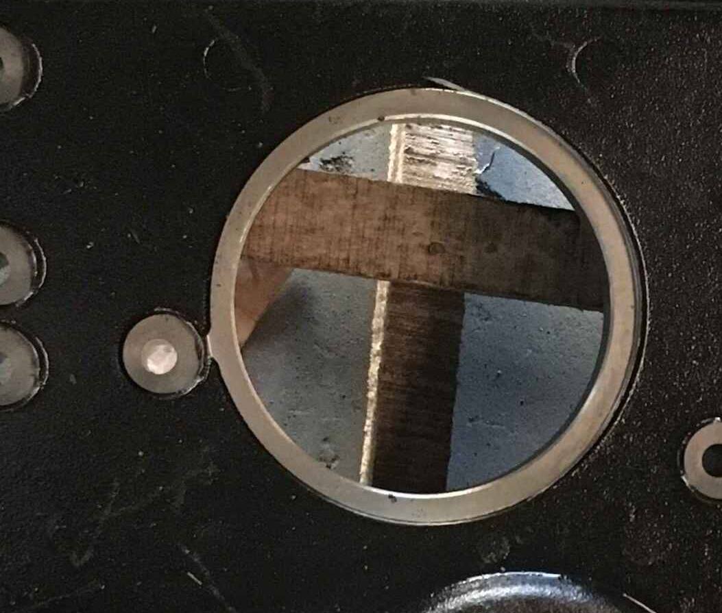
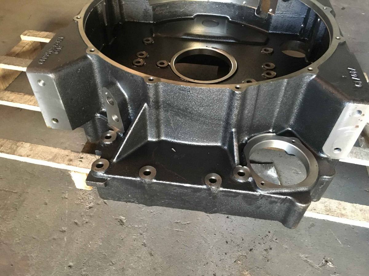
The bore wall in the photo is the surface the tip rides on. A burr or a ridge of paint on that wall adds error that belongs to the part, not to the engine.
The pattern tells you shift or replace
The four numbers are more useful than the TIR alone. Where the high and low points sit tells you what kind of error you have.
| What the readings show | What it means | What to do |
|---|---|---|
| Minimum and maximum exactly 180 degrees apart | The whole housing sits off centre | Loosen the bolts, re-seat, retorque and measure again |
| Minimum and maximum at random positions | The bore is out of round | Replace the housing |
| Repeatable reading above the limit, bore round | Housing can still be shifted | Re-seat once, then replace if it does not come in |
| Readings change between attempts | Setup or end play problem | Fix the setup, do not touch the housing |
Cummins states the rule directly. Misalignment is confirmed when the extremes sit exactly 180 degrees apart. An out of round bore produces extremes at random locations. Then the decision: if the bore is round, the housing can be shifted. If the bore is not round, the housing must be replaced.
This is the part most workshops skip. A housing bolted down off centre can often be brought back by loosening, cleaning and retorquing in sequence. A housing with a distorted bore cannot be saved by shifting, and no clutch will survive it.
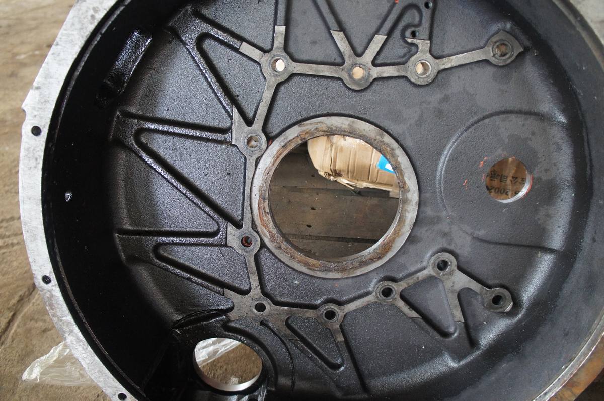
Face runout at the right radius
The face check uses the same points and the same arithmetic. The tip rides on the machined face, as close to the outer edge as the surface allows.
Detroit measures both in one pass, with two indicators on the same post. One reads the bore, the other reads the bolting flange face. Both must come in under 0.33 mm on Series 60 and Series 50.
If the face is out and the bore is good, look at the joint before blaming the casting. Dirt, a burr around a bolt hole, or a bent flange from an earlier accident tilts the face without moving the bore.
Flywheel face runout scales with radius
The flywheel is measured after it is bolted on, and its limit is not a fixed number. It scales with radius.
Detroit Series 60 gives the rule as 0.001 in per inch of radius. A 14 inch clutch therefore allows 0.177 mm TIR at the clutch contact face. Cummins N14 prints the same rule as a table.
| Radius at the measuring point | Cummins N14 limit |
|---|---|
| 203 mm (8 in) | 0.203 mm (0.008 in) |
| 254 mm (10 in) | 0.254 mm (0.010 in) |
| 305 mm (12 in) | 0.305 mm (0.012 in) |
| 356 mm (14 in) | 0.356 mm (0.014 in) |
| 406 mm (16 in) | 0.406 mm (0.016 in) |
Two more flywheel figures are worth keeping. Cummins ISX11.9 gives a maximum of 0.127 mm TIR for flywheel bore runout. Detroit Series 55 gives 0.08 mm at the clutch contact face. Both are tighter than most housing limits, which is the point: a good housing with a bad flywheel still fails.
A flywheel out of limit is removed, and its mounting face is checked for nicks, burrs and dirt before refitting. If it stays out, the flywheel is replaced. Bending one back is not a repair.
Housing bolt torque
Housing bolts decide whether the joint stays put, and the values differ by bolt size.
| Engine | Bolt size | Torque |
|---|---|---|
| Cummins N14 | not stated in the procedure | 203 N·m (150 lb-ft), in the sequence shown |
| Detroit Series 60 | 12 mm | 112 to 126 N·m |
| Detroit Series 60 | 14 mm | 160 to 200 N·m |
| Detroit Series 50 | 12 mm class | 101 to 126 N·m |
Tighten in the published sequence, in stages. A single pass to full torque pulls one side of the housing down first, and the bore follows it. That is one reason a housing that measured well on the bench measures badly on the engine.
What a misaligned housing damages
The damage shows up on parts that are not the housing. That is why the housing gets missed.
| Symptom | Likely housing cause | Check |
|---|---|---|
| New clutch worn on one side within months | Bore off centre, or dowel bores oval | Bore and face runout |
| Clutch drags, gears crunch when cold | Face not square, release geometry loaded sideways | Face runout and release fork play |
| Input shaft seal weeping early | Shaft running off axis | Runout, plus pilot bearing and seal |
| Starter pinion grinds, ring gear teeth chewed | Wrong housing depth or worn starter pocket | Pinion mesh depth and pocket flatness |
| Speed signal unstable, fault code | Sensor bore distorted or loose | Sensor air gap and bore condition |
| Oil at the lower drain hole | Rear crank seal or gearbox input seal | Oil colour, and which side is wet |
The starter row surprises people. A housing a few millimetres too deep moves the pinion away from the ring gear. The starter still turns, the engine still starts, and the ring gear loses teeth over a season.
Causes that live on the housing
Most out of limit housings are not cracked. They are distorted, dirty or worn at the locating features.
Dirt in the joint is the most common and the easiest to fix. Detroit and Cummins both name it first. Blasting grit, paint and old gasket keep the housing from seating flat.
Worn dowel bores come next. The housing locates on dowels, and those bores go oval over a million kilometres. Aftermarket reaming kits exist for this, with oversize reamers around 0.514, 0.561 and 0.623 inch for Cummins NT, NH, N14 and ISX platforms, plus matched dowels. Reaming restores the locating reference, but it is a machined operation, not a file and hammer job.
Casting and machining defects come third. A housing machined with the bore and the face out of square will be out of limit from new. So will one clamped distorted during machining that sprang back after unbolting.
Weld repair is the last one, and the answer is short. A cracked housing that carries an alignment reference should be replaced. Welding cast iron needs preheat and controlled cooling, and even a sound weld can move the bore and the face. A repaired bracket is one thing, a repaired pilot bore is another.
What we machine and what we check
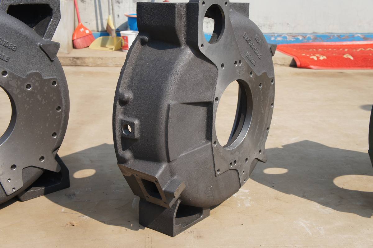
The housings we cast are grey iron, and the two alignment surfaces are machined. The photo below shows the number cast into the outside of one of them, 612600010012, with a second line of moulding or date data beneath it. The rest of the body stays as cast, ribs included.
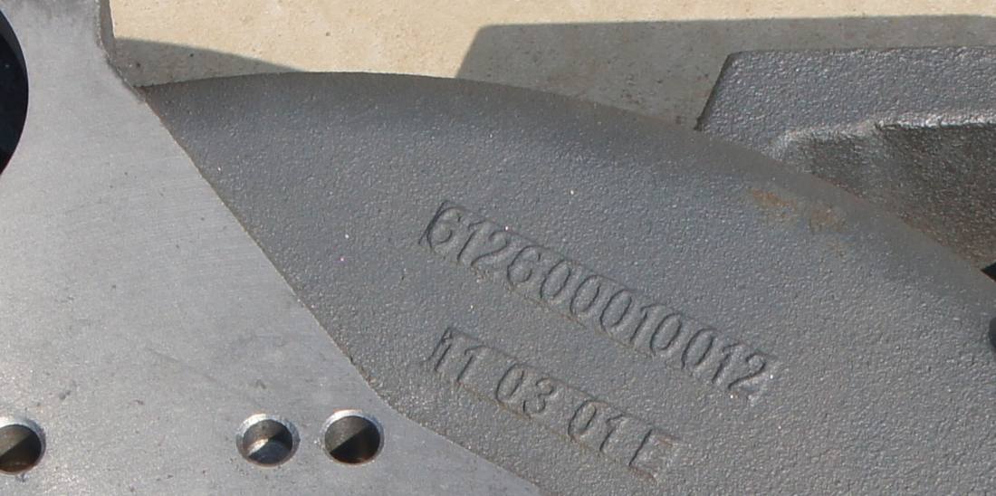
The machining sequence matters more than the machine. The bore and the flange face are cut from the same reference, and the housing is supported so that clamping does not distort it. A housing clamped hard on a flexible flange can measure round on the table and out of round on the engine.
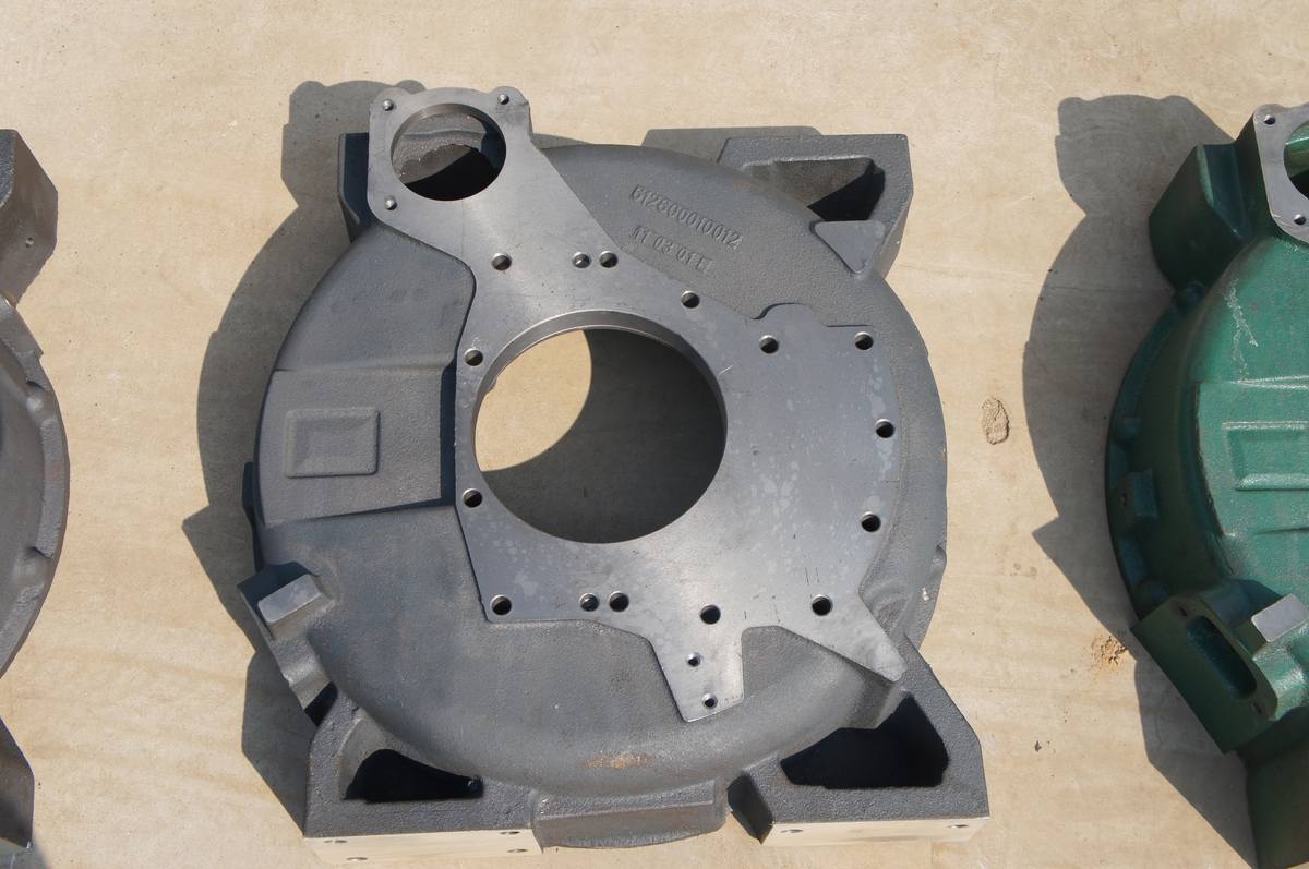
On a housing drawing, the dimensions that decide whether the part works are the bore diameter and its roundness, the flatness of the mating face, the position of the starter bore and the position of the sensor bore. Where a customer supplies a drawing, those are the dimensions we work to. Where the customer supplies only an OE number, we work to the OEM geometry and confirm the interface dimensions before production.
Specifying a replacement housing
A housing is not a part to choose by eye. Two housings can share an SAE size and still differ in the features that make them fit.
| Check | Why it decides the part |
|---|---|
| SAE housing size | Sets the pilot bore and the bolt circle |
| Pilot bore diameter and depth | Sets how far the gearbox spigot enters |
| Starter side and pocket depth | Sets pinion mesh with the ring gear |
| Sensor bore position and size | Sets the speed signal gap |
| PTO opening side and size | Left, centre and right are different castings |
| Dowel hole size and condition | Sets the alignment reference itself |
| Block side bolt pattern and gasket face | Sets what it bolts to |
| Cast or dot peened number | Confirms identity before shipping |
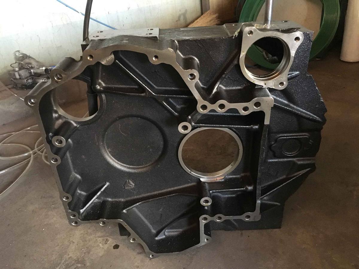
The number on the part, not the shape, is what settles the identity. Two housings from one family can differ in the PTO opening and the sensor bore while looking almost the same from the bell side.
Questions we get from workshops
Is face runout the same as flatness?
No. Flatness is a property of the surface on its own. Face runout is measured with the housing bolted to the engine, so it includes how the housing sits on the block. A flat face can still show high runout if the joint is dirty or the block face is damaged.
Can I check the housing with the gearbox still in the truck?
No. The gauge has to reach the bore and the face, and both sit behind the gearbox bell. The gearbox comes out first. That is the practical reason the check gets skipped, and the reason a repeat clutch failure costs more than the first job.
The bore reads good but the clutch still wears on one side. Where else do I look?
Check the flywheel face runout, then the pilot bearing bore in the flywheel, then the gearbox input shaft and its bearing. Eaton lists 0.005 in for the flywheel pilot bore and 0.003 in for the clutch housing face and pilot on SAE 1 and 2 housings. A worn transmission pilot lip also wears into the housing, usually between the 3 and 8 o’clock positions.
How much runout is acceptable on a housing I just bought?
Use the engine maker’s limit for that engine and that housing size. The SAE J617 values are interface tolerances, not a wear allowance. A new housing should sit comfortably inside them, and both the bore and the face should be checked before installation.
Does an aluminium housing behave differently?
The limits are the same, but aluminium forgives less. Over-torquing, assembly onto a dirty face and forcing alignment all damage an aluminium housing faster than a cast iron one. Thread engagement also needs to be longer: SAE J617 calls for 1.5 times the bolt diameter in grey iron and 2 times in aluminium.
Can a cracked housing be welded and reused?
If the crack touches the flange, a dowel bore or the pilot bore, replace it. Those are alignment surfaces, and welding moves them. A crack on a non-load-bearing bracket is a different conversation, and it needs an expert assessment rather than a decision made in the yard.
Send the housing number and photos
If you are replacing a flywheel housing, send the number on the part, the engine model and two photos: one of the bell side and one of the block side. We will confirm the SAE size, the bore, the starter side and the PTO opening before quoting. Drawing-based parts are welcome too; we machine to the drawing and confirm the interface dimensions first.
For the matching parts, see our flywheel housing range, the ring gears that wear when a starter sits too far out, and the full product list. Background reading: SAE housing sizes and PTO openings, Weichai housing part numbers and flywheel timing marks.
Send your part number and photos through the quote form and we will reply with the interface check and a price.