
Generator Flywheel vs Vehicle Flywheel: Key Differences in Design & Application
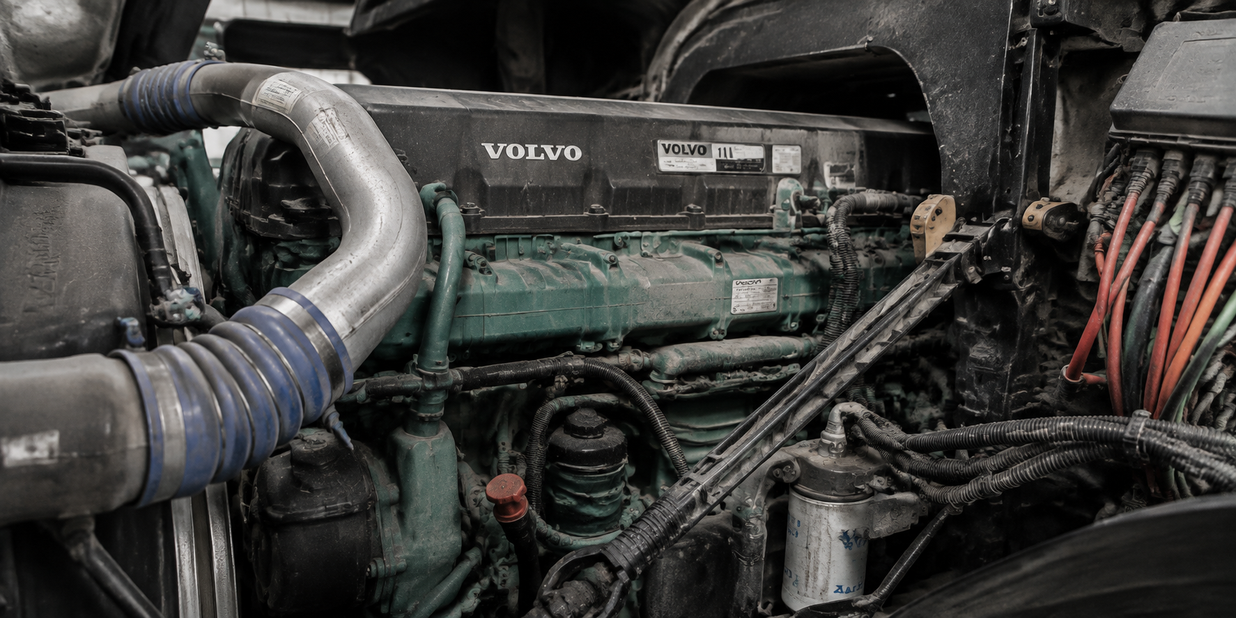
Flywheels appear in both vehicle engines and generator set engines, performing the same basic job: they store rotational energy, carry the crankshaft through power pulses, and provide the interface between the engine and the driven equipment. But a flywheel built for a truck is not the same part as a flywheel built for a generator set. The interface, the operating profile, and the engineering priorities are different — and those differences decide whether a generator runs smoothly for thousands of hours or shakes itself apart.
This guide explains the key differences between generator flywheels and vehicle flywheels, why they exist, and why the integrated connection ring has become the professional standard for generator set applications — especially across Cummins engine platforms.
Fundamental Design Differences
Interface Destination: Transmission vs Generator Coupling
The most important difference is what the flywheel connects to.
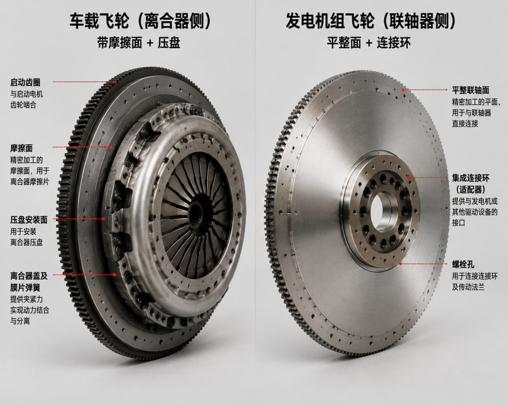
A vehicle flywheel engages a clutch and transmission. Its outer face provides a friction surface for the clutch disc, a bolt pattern and dowel locations matching the clutch cover, and a step or flat configuration optimized for clutch engagement — single-step for solid flywheels, dual-step for dual-mass designs.
A generator flywheel connects to a generator coupling that transfers rotational energy to the alternator continuously. It provides a coupling interface with a defined pilot diameter, bolt pattern, and alignment features, plus a flat machined surface for the coupling connection plate. There is no clutch engagement mechanism — the connection is permanent and continuous during operation.
These two destinations drive completely different dimensional specs, surface requirements, and structural priorities.
Operating Profile: Variable Speed vs Constant Speed
Vehicle engines sweep a wide RPM range. The flywheel sees speed changes from idle to redline, intermittent clutch engagement with transient torque loads, and vibration that shifts in frequency and amplitude as engine speed changes.
Generator set engines run at a fixed speed set by the required electrical frequency — typically 1500 RPM for 50 Hz systems or 1800 RPM for 60 Hz systems. The flywheel sees constant speed throughout operation, continuous torque through the coupling, and — critically — constant vibration frequency and amplitude if any imbalance exists.
The implication is direct: a small imbalance in a vehicle is tolerable because the vibration frequency keeps moving. In a generator set, the same imbalance produces sustained vibration at a fixed frequency, which accelerates fatigue and shortens service life.
The Built-In Connection Ring: The Defining Feature
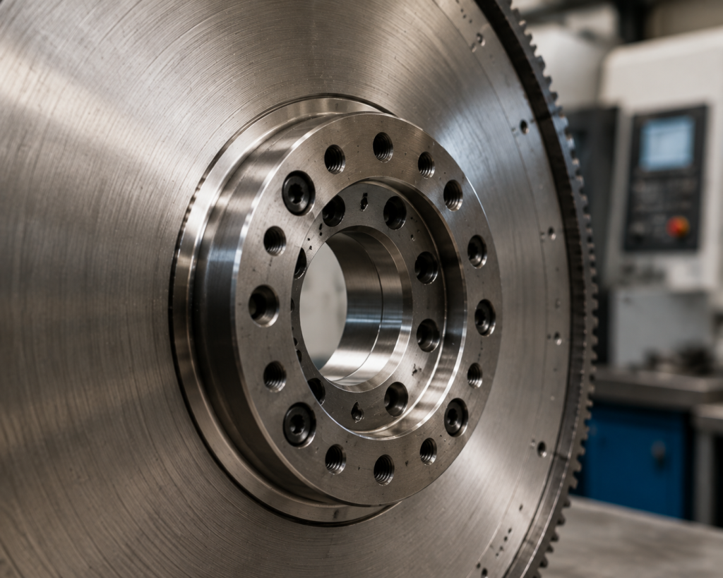
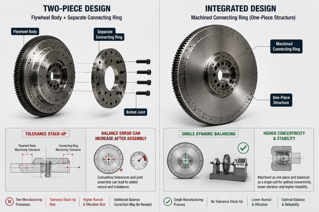
The single biggest difference between a generator flywheel and a vehicle flywheel is that generator flywheels typically carry the connection ring built directly into the part. This integrated design eliminates the four problems that appear when you bolt a separate connection ring to a vehicle flywheel:
- Vibration during operation — Two individually balanced components bolted together accumulate tolerance, producing imbalance under the constant-speed operation of a generator set.
- Dynamic balance tolerance accumulation — Each part is made within its own tolerance. Combined, those tolerances can stack beyond what either part alone would meet. An integrated flywheel is balanced in a single operation, so there is no stacking.
- Operational instability — A bolted joint relies on fasteners that can fatigue, loosen, or misalign under sustained load. An integrated design has no such joint.
- Installation complexity — A two-piece system adds an alignment and bolting step, with more fasteners and more chances for error. The integrated flywheel removes that step entirely.
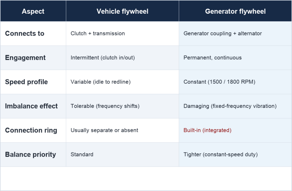
Generator vs Vehicle Flywheel at a Glance
The Tolerance Accumulation Problem
When a flywheel and a separate connection ring are bolted together, each carries its own balance tolerance. The combined assembly can hold imbalance up to the sum of both individual tolerances — and that worst case is always possible, because the assembler positions the ring by bolt pattern, not by balance vector orientation.
In a vehicle, this random variation is hidden by changing RPM. In a generator set, the engine holds a fixed speed, so any imbalance becomes sustained, fixed-frequency vibration — fundamentally more damaging than intermittent vibration.
An integrated flywheel solves this because the entire component is balanced in one operation. No random combination of separate tolerance vectors; the balance specification is achieved directly on the finished part.
Engine Models Where Integrated Connection Rings Apply
The integrated flywheel approach with a built-in connection ring applies across the Cummins engine families used in generator sets.
Cummins 15N (13×12) and RSG Series
Widely used in generator set applications. A vehicle flywheel can be adapted with a separate connection ring, but at production volume an integrated flywheel eliminates the tolerance and assembly issues of the two-piece approach.
Cummins QSM Series
Mid-range generator set engines. The integrated approach delivers the same balance and installation advantages.
Cummins Z13 / Z14 Series
Specific generator set configurations. The integrated connection ring applies, with flywheel specs tailored to the engine model and the generator coupling requirements.
Cummins KTA Series
High-output generator set engines. At these power levels, flywheel balance and reliability are especially critical — sustained imbalance can cause significant vibration in large sets. The integrated approach provides the balance control these demanding applications need.
Cummins QSK Series
Cummins’ highest-output generator set engines. The integrated connection ring’s balance and reliability advantages matter most for large continuous-duty installations.
For all of these platforms, using a flywheel with an integrated connection ring is the professional solution that ensures reliability and simplifies assembly. The same principle — eliminating tolerance accumulation and vibration through single-component design — applies across the entire range. This is also where part-number discipline matters: two flywheels can look identical and even share a suffix, yet carry different full part numbers for different engine platforms and coupling specs. We covered that trap in detail in our guide on why the same flywheel part number suffix can hide a different part — always read the full number, not just the last four digits.
Design Specifications: What Makes a Generator Flywheel Different
Dimensional Specifications
A generator flywheel with an integrated connection ring must meet specifications on two separate interfaces on the same component:
Engine-side interface (must match the vehicle flywheel exactly):
- Crankshaft bolt pattern — number, diameter, and position of bolts to the crankshaft flange.
- Pilot bore — aligns the flywheel on the crankshaft; must match engine specification precisely.
- Timing reference — position of timing marks that align with the engine’s injection timing system.
- Ring gear specifications — tooth count, pitch, and pressure angle must match the starter motor, if present.
Generator-side interface (replaces the separate connection ring):
- Coupling pilot diameter — aligns the generator coupling on the flywheel.
- Coupling bolt pattern — number, diameter, and position of bolts to the coupling.
- Face flatness and surface finish — the mating surface for the coupling plate must meet flatness and finish specs.
- Depth/step dimensions — any steps or relief features that position the coupling at the correct depth.
Both interfaces must be present on one component, with their positional relationship precisely controlled during machining.
Balance Specifications
Generator flywheels require tighter balance specifications than vehicle flywheels in most applications, for three reasons:
- Constant-speed operation — residual imbalance produces sustained vibration at a fixed frequency, more damaging than variable-frequency vibration.
- Extended operating hours — generator sets often run thousands of hours between service intervals, so any vibration condition persists.
- Coupling sensitivity — generator couplings are built for smooth, continuous torque transfer; flywheel imbalance affects coupling alignment and bearing loads.
An integrated flywheel’s single-component balance approach naturally achieves better, more consistent balance quality than a two-piece system’s accumulated tolerances.
Manufacturing and Quality Control
Generator flywheels with integrated connection rings require CNC machining that produces both interfaces on the same workpiece. Vertical CNC lathes machine the rotational surfaces, machining centers create the bolt patterns, and gear hobbing machines produce the starter ring gears. The key advantage is that both interfaces are machined in coordinated setups, holding positional accuracy that would otherwise depend on the combined tolerances of two separate parts.
CMM inspection verifies both engine-side and generator-side dimensions and their positional relationship. As an IATF 16949 certified manufacturer with CMM inspection equipment, Changwei performs these inspections on all integrated flywheel production.
Sourcing Guide
When sourcing generator flywheels, evaluate suppliers on certification (IATF 16949 / ISO 9001), manufacturing capability (CNC lathes, machining centers, CMM), engine platform coverage, application experience, and engineering support. With 20+ years of engine industry experience and flywheel production across 8 product series, Changwei provides the manufacturing capability and engineering support needed for generator set flywheel applications.
Conclusion
The differences between generator flywheels and vehicle flywheels come from their different operating conditions and interface requirements. Generator flywheels run at constant speed for long periods, connect to generator couplings rather than transmissions, and — most importantly — typically incorporate the connection ring directly into the design.
This integrated connection ring approach resolves the four critical problems of the two-piece system: vibration, dynamic balance tolerance accumulation, operational instability, and installation complexity. For Cummins 15N, RSG, QSM, Z13/Z14, KTA, and QSK engines — and for other generator set platforms — the built-in connection ring is the professional design choice that ensures reliability and simplifies assembly.
For specific generator flywheel requirements across these engine platforms, contact our engineering team to discuss integrated flywheel solutions for your applications.
About Changwei: Weifang Changwei Intelligent Equipment Co., Ltd. is an IATF 16949 certified engine flywheel manufacturer based in Weifang, China. With a 40,000 sqm production facility and 20+ years of engineering expertise, Changwei supplies flywheels, gear rings, and housing parts to customers in 20+ countries. Contact us for OEM/ODM flywheel solutions.