
Ring Gear Interference Fit: The Math Behind the Shrink Fit
Ring Gear Interference Fit: The Math Behind the Shrink Fit
A ring gear is not bolted to a flywheel. It is gripped onto it.
Heat the gear past 200 °C, its bore grows by a few tenths of a millimetre, drop it over the machined shoulder on the flywheel, and let it cool. As it cools, it contracts and clamps down. From that moment on, torque is transmitted by friction alone. No key, no dowel, no weld.
In repair shops this often gets treated as a feel job: play a torch over it, judge the colour, drop it on. But whether the gear will slip or crack is decided by a set of numbers, and those numbers can be worked out in advance.
This article covers three things: where the interference figure comes from, why the heating temperature has a basis, and what a ±0.04 mm bore tolerance on a ring gear actually consumes out of the assembly window.
Table of Contents
- Why an interference fit transmits torque
- One dimension chain, three numbers
- Δt = δ / (α × d): the heating temperature is not a guess
- 0.001 inch per inch: the rule of thumb
- A ±0.04 mm bore tolerance eats 23% of the window
- Uneven heating shortens ring gear life
- The one check that has to happen after assembly
- The short version
Why an Interference Fit Transmits Torque
Start with how the force path works.
Once the gear has cooled, its bore is slightly smaller than the flywheel shoulder. That difference is the interference. The gear wants to contract back to its original size; the flywheel shoulder stops it. The gear’s bore wall ends up in tension, the shoulder in compression. That pair of forces produces radial pressure at the contact face, and radial pressure multiplied by the friction coefficient gives the tangential friction available.
Every bit of the starting torque comes through that friction. So:
- Too little interference → not enough friction → the gear slips under high torque, wears, and eventually stops turning the starter
- Too much interference → bore wall tension gets too high → cracking risk, and the gear is more likely to jam during assembly
Both extremes fail. In between there is a window, and the engineering job is to land the actual interference inside it.
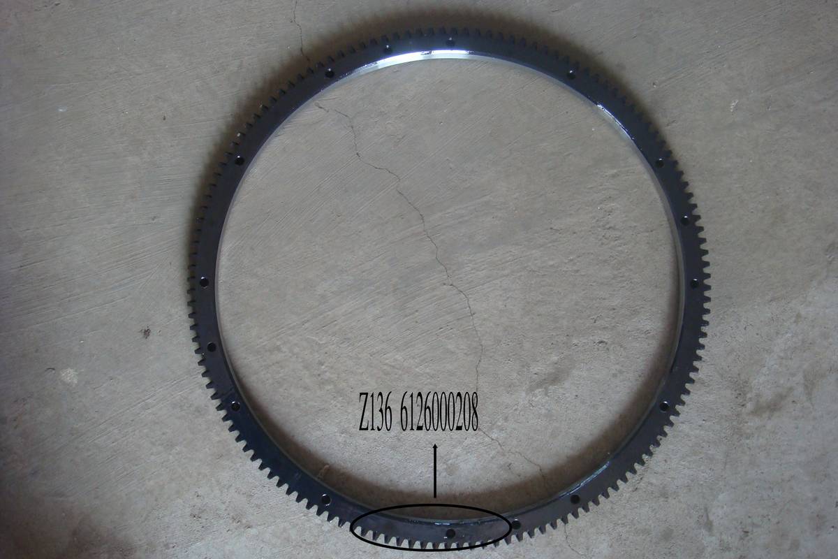
A ring gear marked Z136. The area highlighted is the relationship between the bore and the teeth. What actually grips the flywheel is this bore surface. The teeth only mesh with the starter pinion and carry no torque.
One Dimension Chain, Three Numbers
The interference figure is not a standalone number. It is the result of a dimension chain:
Flywheel shoulder OD − ring gear bore ID = interference
The Detroit Diesel MBE 4000 manual publishes all three, and it makes a good worked example:
| Item | MBE 4000 spec (mm) |
|---|---|
| Flywheel shoulder diameter (for ring gear mounting) | 432.450 – 432.645 |
| Ring gear inside diameter | 432.000 – 432.155 |
| Ring gear / flywheel interference fit | 0.295 – 0.645 |
| Ring gear permissible radial runout | 0.5 |
| Ring gear fitting temperature | 200 – 230 °C |
The manual’s own inspection method is one sentence: measure the flywheel shoulder diameter, measure the ring gear inside diameter, subtract, and the result has to fall between 0.295 and 0.645 mm.
Note that every dimension in that chain carries its own tolerance band. The shoulder has a 0.195 mm band (432.450–432.645). The ring gear bore has a 0.155 mm band (432.000–432.155). The target window is 0.350 mm wide. In other words, if both parts sit at the extreme ends of their own tolerance bands — shoulder at max with bore at min gives 0.645; shoulder at min with bore at max gives 0.295 — the window is exactly consumed.
That leads to a practical question. What happens if the ring gear bore tolerance is opened up a little? Section 5 works it through with a real drawing.
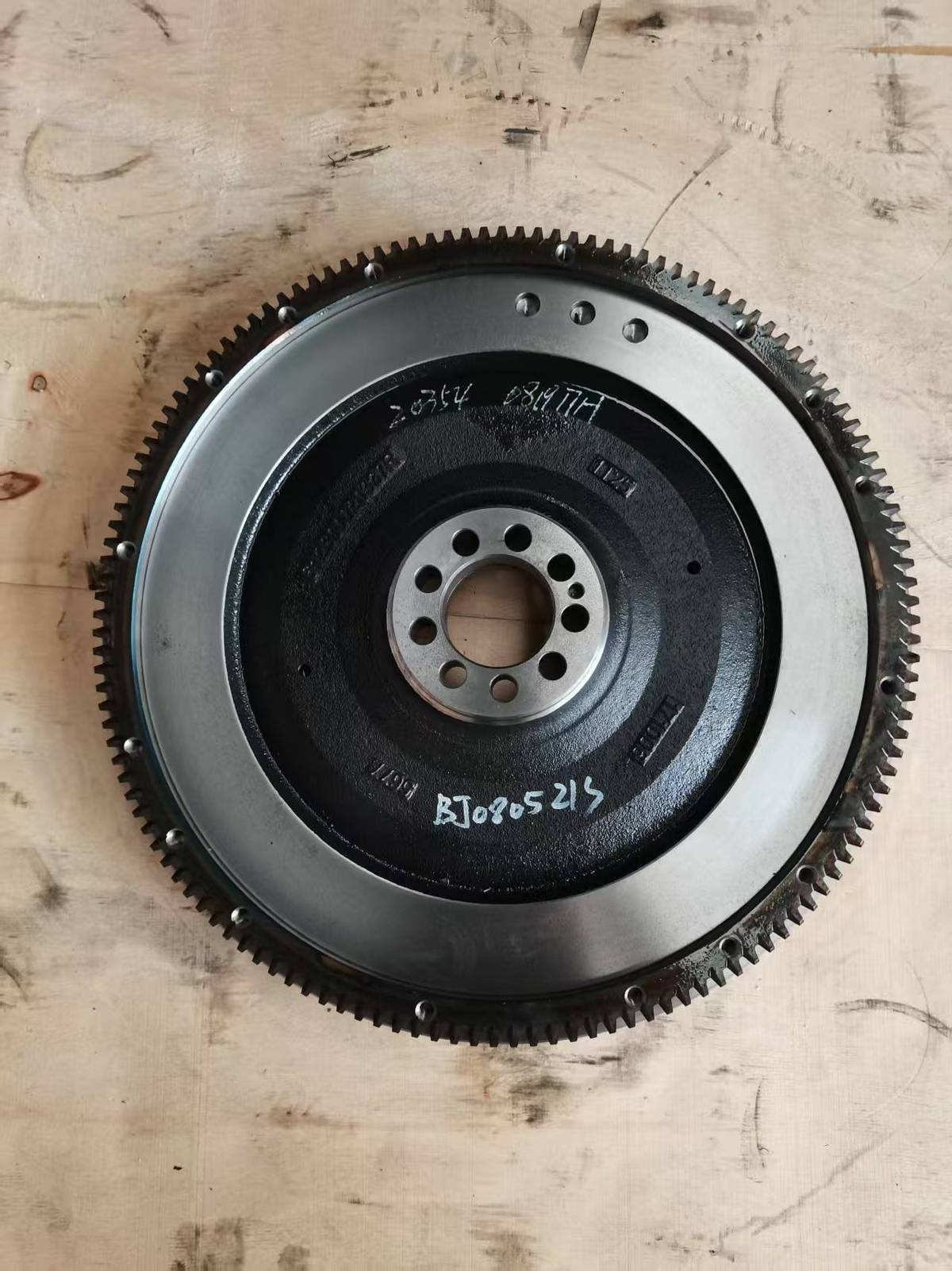
A complete flywheel assembly (Weichai 20354 series). The ring gear is already in place on the outer shoulder. In production this is a single balanced unit — but the gear and the flywheel are two separately toleranced parts, and their tolerances add up at the joint.
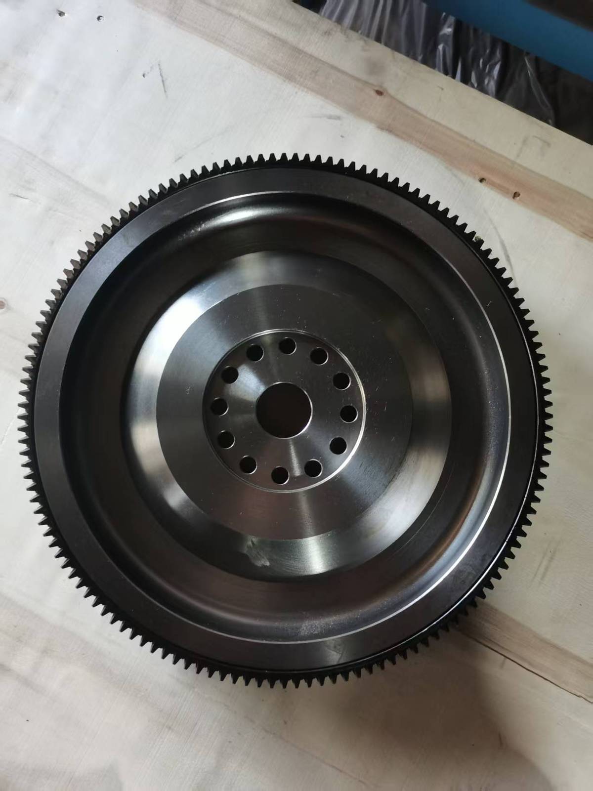
A flywheel assembly with the ring gear already pressed on. The gear sits on the machined shoulder at the outer edge and grips once it cools. Removal means heating and pressing it off — there is no releasable fastener anywhere in the joint.
Δt = δ / (α × d): the heating temperature is not a guess
How hot to heat it can be calculated. The derivation is direct.
Steel expands linearly with heat: change in diameter = coefficient of linear expansion × temperature rise × original diameter
As a formula:
Δt = δ / (α × d)
- Δt = required temperature rise (K)
- δ = required diametric expansion (mm), at minimum equal to the interference, in practice with margin
- α = coefficient of linear expansion (steel / cast iron, about 11.7 × 10⁻⁶ /K)
- d = bore diameter before expansion (mm)
Put the MBE 4000 numbers in. Bore 432 mm, maximum interference 0.645 mm. To grow the bore by 0.645 mm so it will just drop on:
Δt = 0.645 / (11.7 × 10⁻⁶ × 432) = 128 K
From a 20 °C ambient that is about 148 °C. The manual calls for 200–230 °C, a rise of 180–210 K — clearly above the theoretical minimum. That extra margin covers two things:
- The gear loses heat between coming out of the oven and being seated
- The moment the gear touches the flywheel anywhere, heat transfers and that local expansion is gone
So a manual temperature is always above the calculated minimum. Conversely: if your calculated minimum rise is already close to the manual’s temperature, the fit is too tight and the design should be revisited.
0.001 Inch per Inch: The Rule of Thumb
When there is no manual figure to hand, the industry has used a rule of thumb for decades:
Interference = 0.001 inch per inch of diameter
That works out to roughly 0.001 mm per mm of diameter. For example:
| Ring gear bore | Interference per the rule |
|---|---|
| Ø119 mm | about 0.12 mm |
| Ø350 mm | about 0.35 mm |
| Ø432 mm | about 0.43 mm |
Against the MBE 4000 published window of 0.295–0.645 mm at a 432 mm bore, the rule gives 0.43 mm — comfortably inside, a little above the middle. That makes the rule a sensible starting point, not a precise value. It tells you the order of magnitude; the final number comes from the OEM drawing.
The dangerous use is the reverse. Applying a 0.43 mm interference to a small Ø119 mm gear because that is what a large gear uses will produce far higher contact stress at the smaller diameter. Small gears crack first.
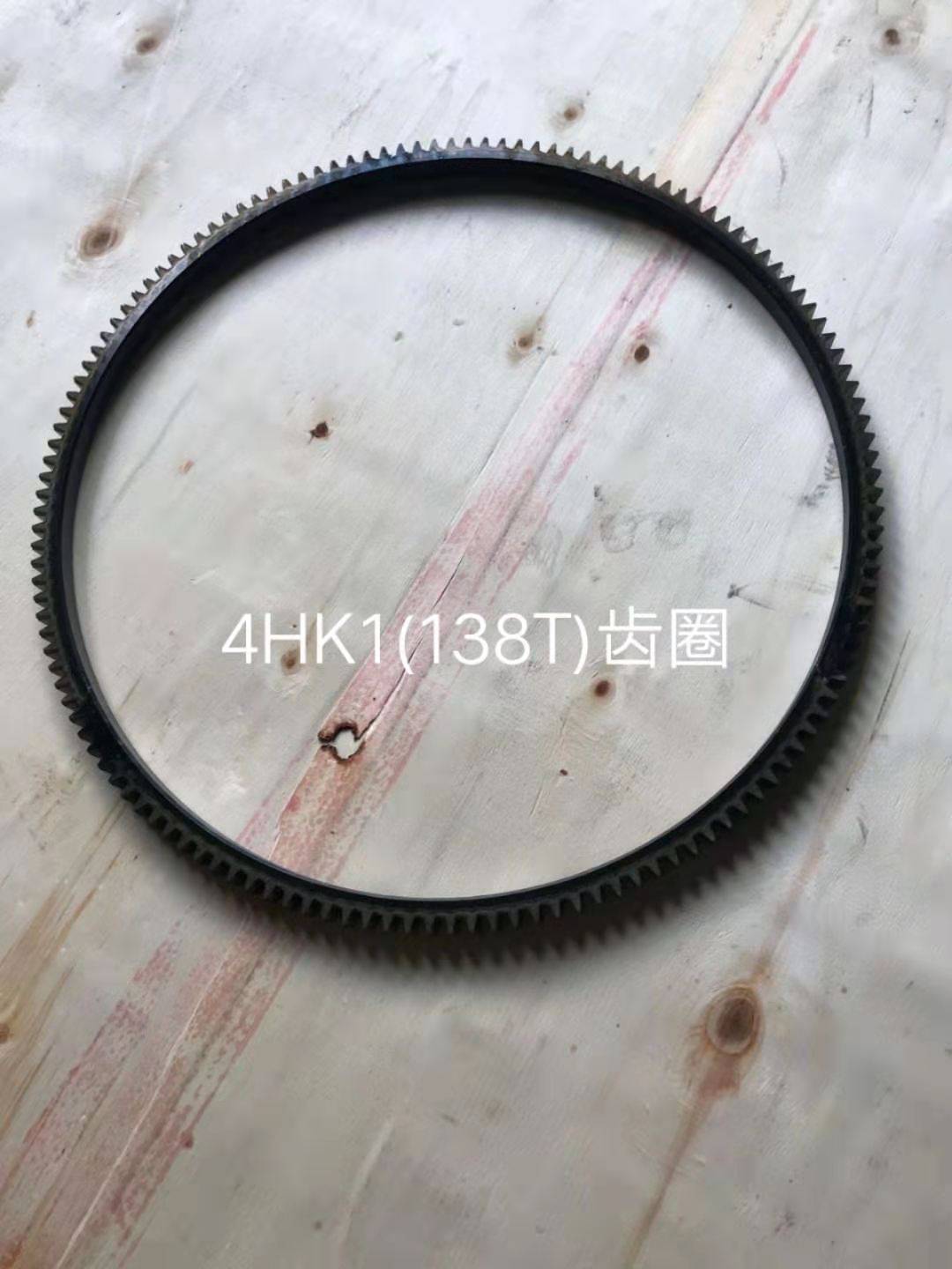
An ISUZU 4HK1 ring gear, 138 teeth. Different engine families use different tooth counts and different bores — which means the interference figure has to be worked out per application, not carried over from whichever drawing is closest to hand.
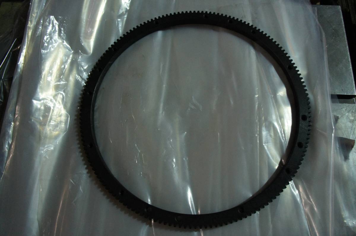
A ring gear in the loose condition. In this state the bore can be measured directly with an inside micrometer. Interference acceptance is exactly this: the bore measured here, minus the flywheel shoulder OD.
A ±0.04 mm Bore Tolerance Eats 23% of the Window
Now bring in a real drawing.
We hold two ring gear blank drawings issued in 2010 by a UK customer, RING PLUS AQUA LTD, Starter Gear Division. They are two sizes from the same programme:
| Item | RPAL 111B1431 | RPAL 111B1501 |
|---|---|---|
| Outer diameter | Ø143.95 ± 0.04 | Ø150.95 ± 0.04 |
| Bore | Ø119.0 ± 0.04 | Ø115.0 ± 0.04 |
| Thickness | 29.15 ± 0.04 | 23.95 ± 0.04 |
| Flatness | 0.08 Max (datum A) | 0.08 Max (datum A) |
| Material | SAE 1010 | SAE 1010 |
Look at the bore line: Ø119.0 ± 0.04, a tolerance band 0.08 mm wide.
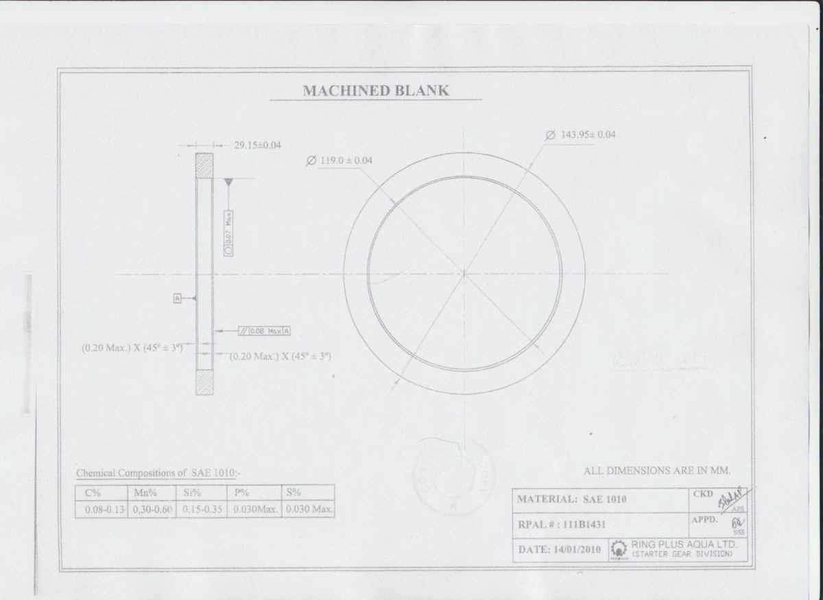
Drawing RPAL 111B1431. OD Ø143.95, bore Ø119.0, thickness 29.15, all three at ±0.04 mm; flatness 0.08 Max referenced to datum A; SAE 1010 chemistry in the corner. We walked through this drawing callout by callout in an earlier article; here we are only looking at the bore line.
Now run a hypothetical assembly. Suppose the customer ultimately pairs it using the MBE 4000 logic: an interference window of 0.295–0.645 mm, 0.350 mm wide, with the flywheel shoulder sized against the ring gear bore nominal.
The problem: the ring gear bore alone occupies a 0.08 mm band.
0.08 ÷ 0.350 = 23%
That single callout, ±0.04 mm, consumes nearly a quarter of the entire assembly window on its own. What is left for the flywheel shoulder, assembly process, temperature control, and measurement error is 0.27 mm — and the flywheel shoulder typically takes 0.15–0.2 mm of band itself.
The conclusion is direct: the ring gear bore tolerance is not a case of “looser is easier to make.” It is the first link in the assembly chain to be tightened. The ±0.04 is not written there casually. Open it up and the assembly line starts sorting parts.
There is a second point in that drawing. It is a blank drawing, marked MACHINED BLANK. The ±0.04 is something the machining operation downstream has to hold. The foundry ships a blank, which means the foundry’s job is to leave enough machining allowance, and leave it even. If the blank is eccentric, one side of the bore cleans up while the other does not — and the finished bore is no longer round, so the tolerance cannot be held no matter how good the machining is.
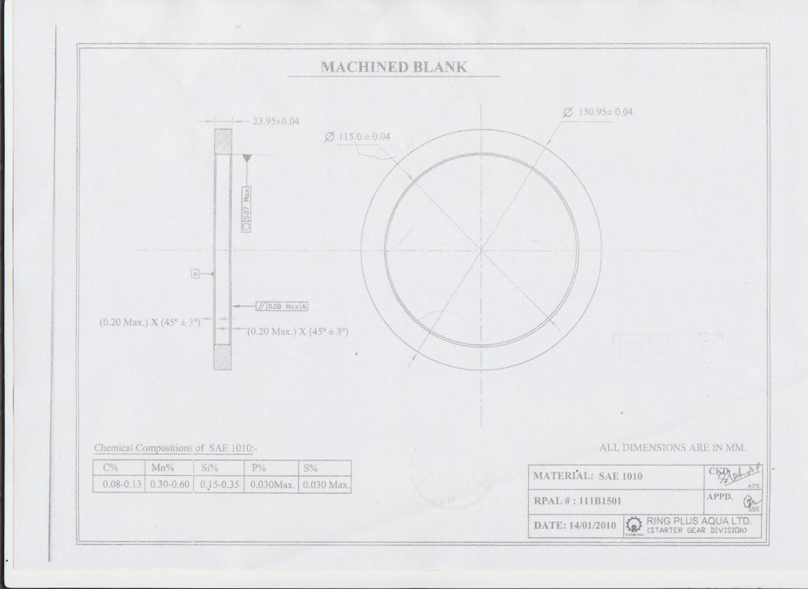
The other drawing in the series, RPAL 111B1501: OD Ø150.95, bore Ø115.0, thickness 23.95. Same customer, same programme, and the bore is again ±0.04 — the tolerance strategy is consistent across the programme, not a one-off on a single sheet.
Uneven Heating Shortens Ring Gear Life
The manuals call this out separately, in warning language.
MBE 4000, in substance: heat the new ring gear as evenly as possible; use an oven if one is available. Uneven heating can weaken the gear and shorten its service life.
Why? Ring gears are usually medium-carbon or alloy steel with induction- or flame-hardened teeth. Playing a torch on one spot drives that area to a high temperature:
- A locally overheated zone can exceed the tempering temperature and soften teeth that were deliberately hardened
- An uneven temperature distribution means the gear goes on crooked — the manual warns about this explicitly
- Once it is crooked, local interference far exceeds the design value and the stress at that spot roughly doubles
The common shop-floor method — playing a torch around the whole ring and judging by colour — is not wrong in itself, provided the heating is even all the way round and the temperature stays below the tempering range. What fails is heating one spot, getting it red, and dropping it on. The teeth at that spot are effectively ruined.
The right approach is an oven or an induction heater so the whole ring comes up together. If flame is the only option, keep the torch moving continuously around the full circumference and never park it.
- Detroit MBE 900: 250–280 °C
- Detroit MBE 4000: 200–230 °C
- Cummins B Series: oven preheat 127 °C (260 °F) for about 20 minutes
- Mitsubishi L Series: about 100 °C
Those four figures range widely — 100 °C to 280 °C. It depends on the interference amount and the cross-sectional stiffness of the gear: more interference and a heavier section need more expansion, hence more heat. So borrowing another engine’s heating temperature is meaningless. Use the value that belongs to your drawing.
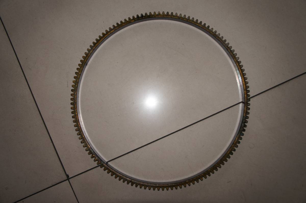
A loose ring gear. The condition it leaves the factory in sets the ceiling on how hot it can be heated — if the teeth are hardened, the heating temperature has to stay below the tempering range or the hardness is gone.
The One Check That Has to Happen After Assembly
The gear is on and has cooled. The job is not finished.
A cooled ring gear retains some of the unevenness from the shrink fit, and the pressing operation itself can distort it slightly. So the manuals require a radial runout check after the gear is pressed on and before the flywheel goes back on the crankshaft:
- Detroit MBE 900: ring gear radial runout allowance 0.5 mm
- Detroit MBE 4000: ring gear radial runout allowance 0.5 mm (0.02 in)
The method is the one from the previous article: use the flywheel’s rotation axis as the datum, turn the part, sweep a dial indicator on the gear’s outer circumference or tooth tips, and take the highest reading minus the lowest.
Note this is an installed value, not a loose-part value. A ring gear on its own can be perfectly round, but if the flywheel shoulder has taper or a burr, the gear gets pushed off-centre as it contracts. So the 0.5 mm cannot be verified until the gear is on.
If it exceeds 0.5 mm, the diagnostic order matches the flywheel runout sequence: check first for burrs or debris between the shoulder and the gear bore, then check the shoulder’s own roundness and runout, and only then judge the gear itself.
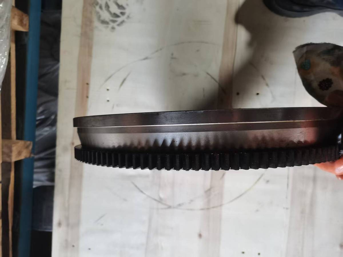
Side view of the assembly. The gear sits on the shoulder at the outer edge of the flywheel. The height and cylindricity of that shoulder decide whether the gear grips evenly — a tapered shoulder leaves the gear off-centre once it cools.
The Short Version
An interference fit is calculated, not judged by feel. The dimension chain is “flywheel shoulder OD − ring gear bore ID = interference.” The heating temperature has a lower bound from Δt = δ / (α × d). Every manual figure sits above that calculated minimum, and the difference is the operating margin.
For a foundry, the number worth remembering is this: a ±0.04 mm bore tolerance on a ring gear consumes 23% of a 0.295–0.645 mm assembly window. That is why blank eccentricity and evenness of machining allowance deserve more attention than the casting tolerance grade on its own. The bore is produced at the final operation, but its roundness is decided back at the casting stage.
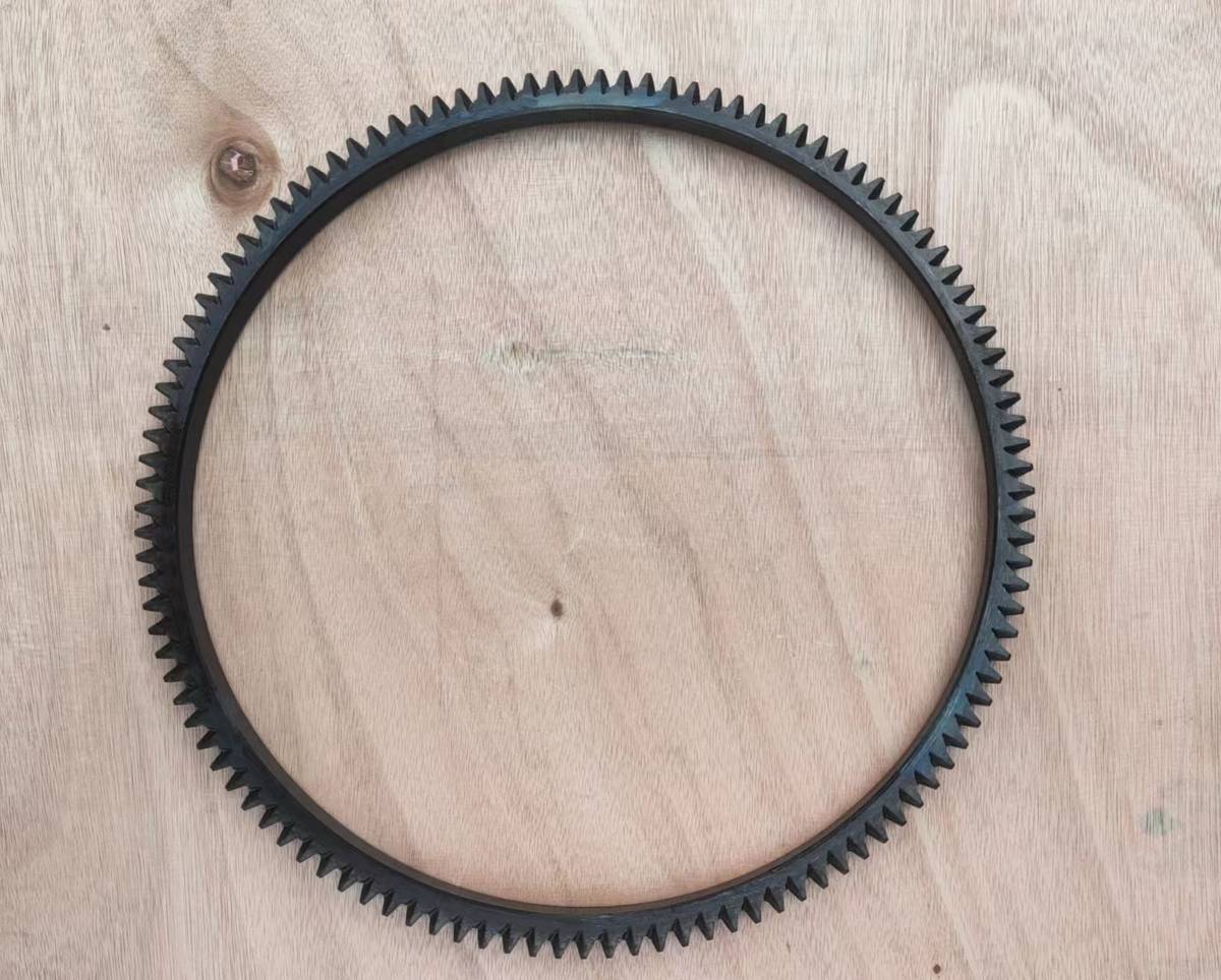
An export-order coarse-pitch ring gear. Coarse pitch gives higher tooth root strength and more tolerance for starter pinion engagement, but cumulative pitch error has a larger effect on radial runout — so it is normally paired with a tighter interference and stricter runout requirement.
About Us
Changwei Intelligent Equipment (Changchai Power) is an IATF 16949 certified iron casting facility in the Wangke Industrial Zone, Changyi, Weifang, Shandong, China. We produce flywheels, ring gears, flywheel housings, timing gear housings, cylinder blocks and heads, and transmission housings in grey and ductile iron. We build to drawing, and we also take samples and drawings for tooling development.
If you have a ring gear or flywheel drawing and want the bore tolerance checked against the assembly interference, send the drawing over. We go through it item by item and tell you plainly which requirements we can hold and which we cannot.
- Email: [email protected]
- Phone / WhatsApp: +86 19953662121
- Address: Wangke Industrial Zone, Changyi, Weifang, Shandong, China
- Terms: FOB Qingdao