
From Drawing to First Article: What Your Customer Drawing Says Before a Foundry Quotes
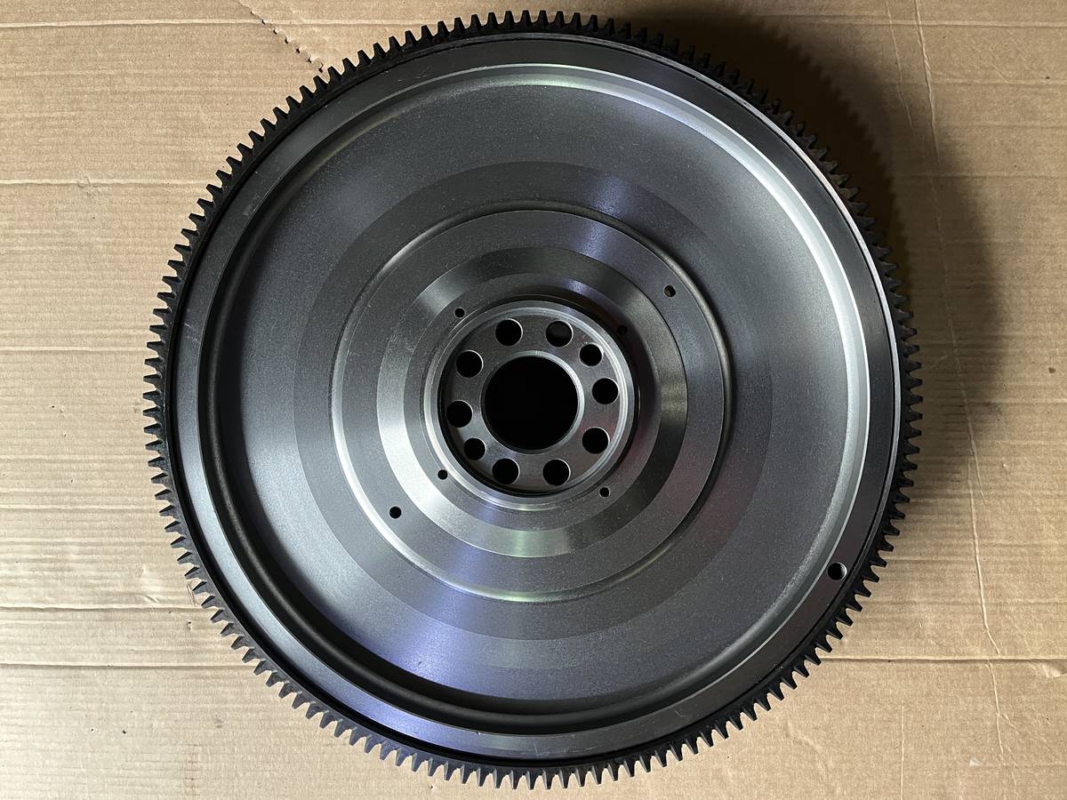
From Drawing to First Article: What Your Customer Drawing Says Before a Foundry Quotes
Most suppliers answer a drawing request with a price. Very few answer it with a list of the things they noticed.
The difference matters, because on a machined casting the price is decided by a handful of callouts that are easy to skim past — an inner diameter with a four-hundredths-of-a-millimetre tolerance, a flatness figure, a chemistry table in the corner. Read them wrong and the part is either quoted too cheap to make or made too loose to fit.
This article walks through a real customer drawing from our files and explains what each element tells a foundry, in the order a foundry actually reads it.
Table of Contents
- The drawing we are looking at
- The title block: what “machined blank” tells you
- The three dimensions that decide everything
- Why flatness is called out separately
- The chemistry table is not decoration
- The chamfer note most people misread
- What changes between the drawing and the first article
- What to send us for a quote, and what you get back
The drawing we are looking at
The drawing below was issued to us by RING PLUS AQUA LTD, Starter Gear Division, dated 14 January 2010. It is a starter ring gear blank, unit RPAL 111B1431. The second drawing in this article is RPAL 111B1501, a different size from the same programme.
We are publishing these because they are a good teaching example, not because ring gear blanks are unusual. Everything on them applies to a flywheel, a flywheel housing, a gear housing or a cylinder head just as well.
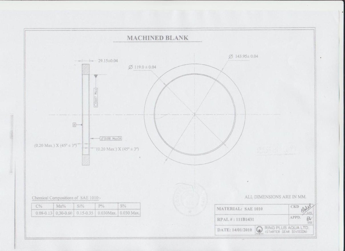
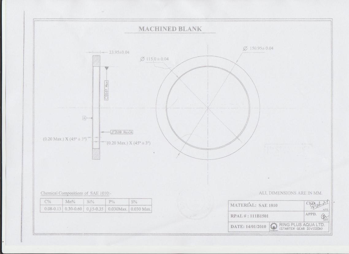
Both drawings carry the same structure: a title, a cross-section on the left, a front view on the right, a chemistry table bottom-left, and a title block bottom-right. That layout is worth learning, because it is close to universal.
The title block: what “machined blank” tells you
The heading on both sheets is MACHINED BLANK. That phrase is doing real work.
A blank is a part that has been brought to final dimensions except for the teeth. The teeth are cut afterwards, by the customer or by a specialist gear cutter, not by the foundry that produced the blank. So the drawing is not asking for a finished ring gear. It is asking for a ring gear that is finished everywhere the gear cutter will use as a datum.
That is why the drawing looks the way it does. The outside diameter, the inside diameter, the thickness and both faces are all toleranced tightly. There is no tooth count on the sheet, no module, no pressure angle — because those belong to the operation that happens next.
This arrangement is standard practice across the industry. Gear blank tolerances typically consume 30 to 50 percent of the total tolerance budget for a finished gear, so a blank that arrives slightly out of specification cannot be recovered later. If the bore is not perpendicular to the face, or the faces are not parallel, the eccentricity shows up as tooth geometry error after cutting, and the whole batch is scrap.
Practically, this means we are not competing on the tooth. We are competing on the datum. The value we add is that the gear cutter can clamp the blank, locate on the bore, indicate the face, and start cutting with confidence.
The three dimensions that decide everything
Look at the numbers on RPAL 111B1431:
| Feature | Value | Tolerance |
|---|---|---|
| Outside diameter | Ø143.95 | ±0.04 mm |
| Inside diameter | Ø119.0 | ±0.04 mm |
| Thickness | 29.15 | ±0.04 mm |
And on RPAL 111B1501:
| Feature | Value | Tolerance |
|---|---|---|
| Outside diameter | Ø150.95 | ±0.04 mm |
| Inside diameter | Ø115.0 | ±0.04 mm |
| Thickness | 23.95 | ±0.04 mm |
Four hundredths of a millimetre. For readers working in inches, that is roughly 0.0016 inches — considerably tighter than a standard machined tolerance, and on a part approaching 151 mm across.
Two things about this are worth stating plainly.
First, the tolerance is symmetric and unpadded. It is not ±0.1, which would allow a turning operation to be done on a conventional lathe with a skilled operator and a hand gauge. At ±0.04 mm on a diameter of this size, you need a controlled process, a machine that holds size through the run, and a gauge capable of resolving a fraction of the tolerance band. The measuring instrument should be able to read at least one tenth of the tolerance — at ±0.04 mm that means resolution to 0.004 mm, which is micrometer or CMM territory, not caliper territory.
Second, the inner diameter is the most important of the three, and it is the one a buyer is least likely to ask about. On a ring gear blank, the bore is the locating feature for the tooth cutting operation and, later, the interference fit onto the flywheel. Both functions depend on the same number. A bore that is on size but out of round will gauge correctly with a two-point micrometer and still fail in service.
This is why we call out bore cylindricity separately in our own process control, even when the drawing does not ask for it. Good practice for a gear blank is to hold cylindricity to no more than half of the bore diameter tolerance. On a ±0.04 mm bore, that means 0.02 mm.
Why flatness is called out separately
On the cross-section there is a boxed symbol reading 0.08 Max with a datum flag A attached to the left-hand face, and the dimension line it sits on points at the large flat face. That is a flatness control: the face must lie within two parallel planes 0.08 mm apart.
It is a small number, and it is specified for a physical reason. The flat face is the axial locating datum. If it is not flat, the part does not seat against the mating surface, and the error transfers straight into whatever is assembled on top of it.
For a flywheel, the equivalent requirement is well established. Published technical specifications for flywheel assemblies put the flatness of the friction face at no more than 0.08 mm — the same figure as this drawing. That convergence is not a coincidence. It reflects what the assembly can tolerate before clutch engagement, runout or vibration becomes a problem.
Note also what the drawing does not say. There is no surface roughness callout on the sheet. In our experience that is common on older drawings, and it leaves a gap: a face can be geometrically flat and still be too rough to seal or to carry a friction surface. When a drawing is silent, we ask. The default we work to on a machined face for this kind of part is Ra 3.2 micrometres or better.
The chemistry table is not decoration
Bottom-left on both sheets is a small table headed Chemical Compositions of SAE 1010:
| Element | Range |
|---|---|
| C | 0.08 – 0.13 |
| Mn | 0.30 – 0.60 |
| Si | 0.15 – 0.35 |
| P | 0.030 Max |
| S | 0.030 Max |
This is the material specification, and it is a low-carbon steel rather than a cast iron. SAE 1010 sits close to Chinese grade 10 steel, with the first pair of digits indicating the manganese level and the second pair the nominal carbon content at around 0.10 percent. It is specified for its combination of low strength, good ductility and excellent machinability, and it can be case hardened afterwards when surface hardness is required.
Three practical points about this table.
The carbon range is narrow, 0.05 percentage points wide. That is a controlled material, not a generic low-carbon steel, and it needs a supplier who can show you a heat number and a mill certificate rather than a verbal assurance.
The phosphorus and sulfur limits are written as maxima, 0.030 percent each. Those two elements are the ones that make steel brittle and hard to machine respectively, and controlling them is a quality criterion in its own right. In practice, the sulfur figure is the one that most often decides whether a part machines cleanly or tears.
The table does not list mechanical properties. No tensile strength, no hardness, no elongation. Where a drawing omits these, they are normally inherited from the material standard, but a buyer should confirm that rather than assume it, particularly if the part will be case hardened after delivery.
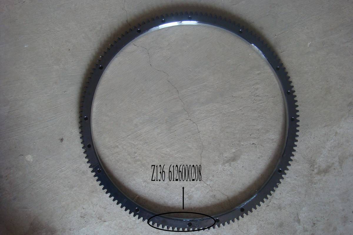
For comparison, here is a finished ring gear from a different programme, marked with its tooth count and part number. This one has already been through the tooth cutting operation that the blank drawings above do not cover:
The chamfer note most people misread
Down the left edge of both cross-sections appears this note, twice:
(0.20 Max.) X (45° ± 3°)
Read it as: a chamfer of 45 degrees, plus or minus 3 degrees, with a maximum leg length of 0.20 mm. The 0.20 is a ceiling, not a target.
Two things go wrong here in practice. The first is treating the chamfer as cosmetic. It is not: a controlled chamfer on a bore edge prevents the sharp corner from raising a burr that would interfere with the locating fit. The second is machining it too generously. Because 0.20 mm is a maximum, a chamfer cut at 0.35 mm fails the drawing even though it looks better.
The tolerance on the angle, ±3 degrees, is comparatively loose. That is deliberate. The function being served is deburring, and deburring does not need a precise angle. It needs a present chamfer of a controlled maximum size.
What changes between the drawing and the first article
A drawing is a promise. A first article is proof. Between the two sits the whole production process, and this is where you learn whether a supplier is a foundry or a trader.
Here is the same part in two states. First, as it comes out of the moulding and cleaning operation — surface still coarse, bores and faces not yet finished, gear teeth already present in the cast form but not yet cut to final profile:
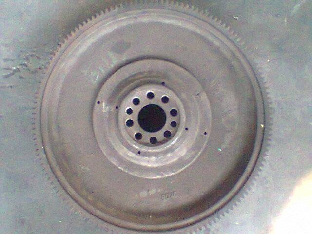
And here is the finished machined part, off the same line. The friction face carries visible concentric turning marks from the finish pass, the centre bore and bolt holes are finished, and the ring gear teeth are cut:
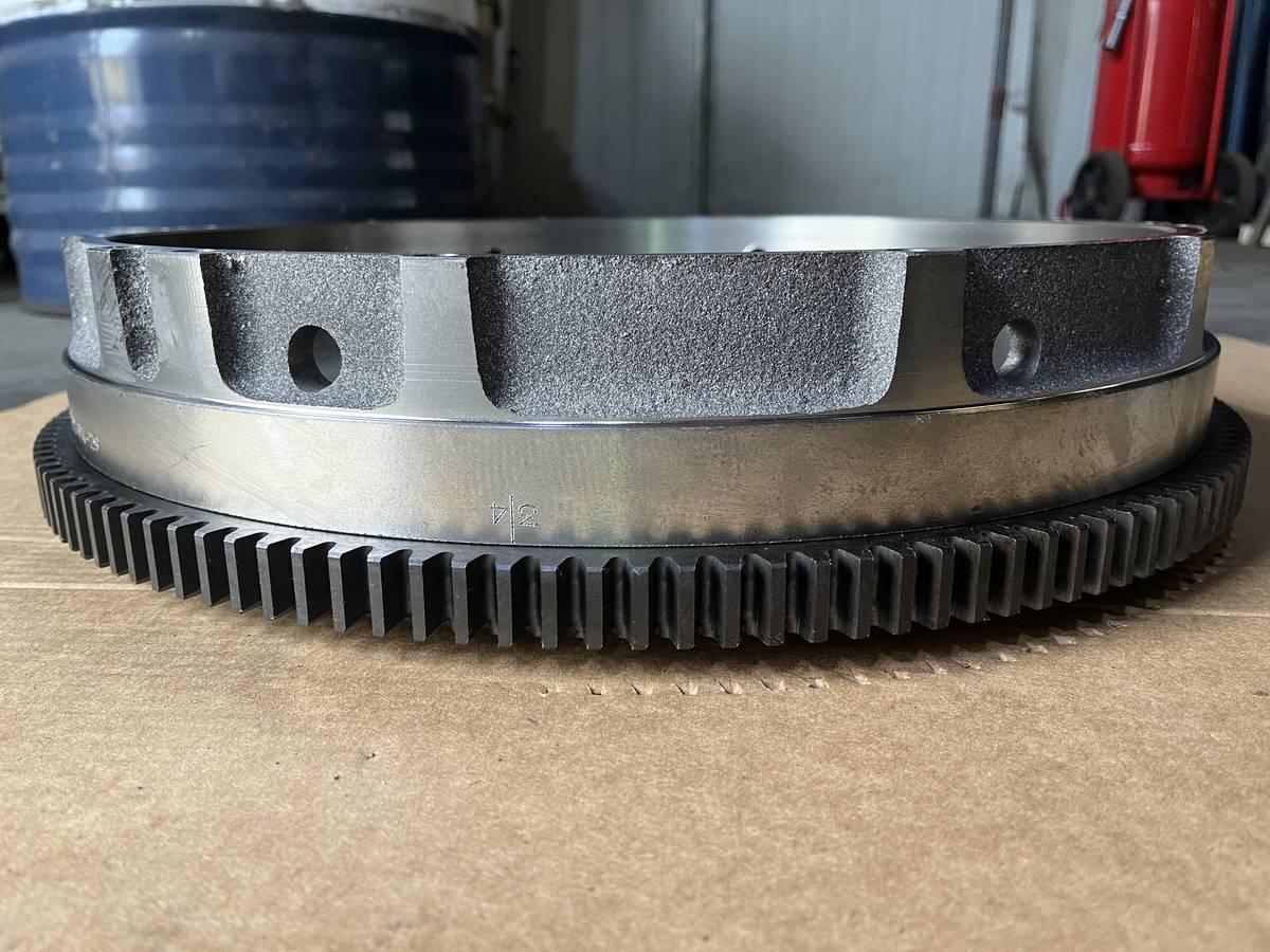
For a first article submission, this is the package we send: the part itself, the dimensional report covering every toleranced feature on the drawing, material certification with the heat number, and photographs of the part in the as-cast and as-machined states so the buyer can see what changed.
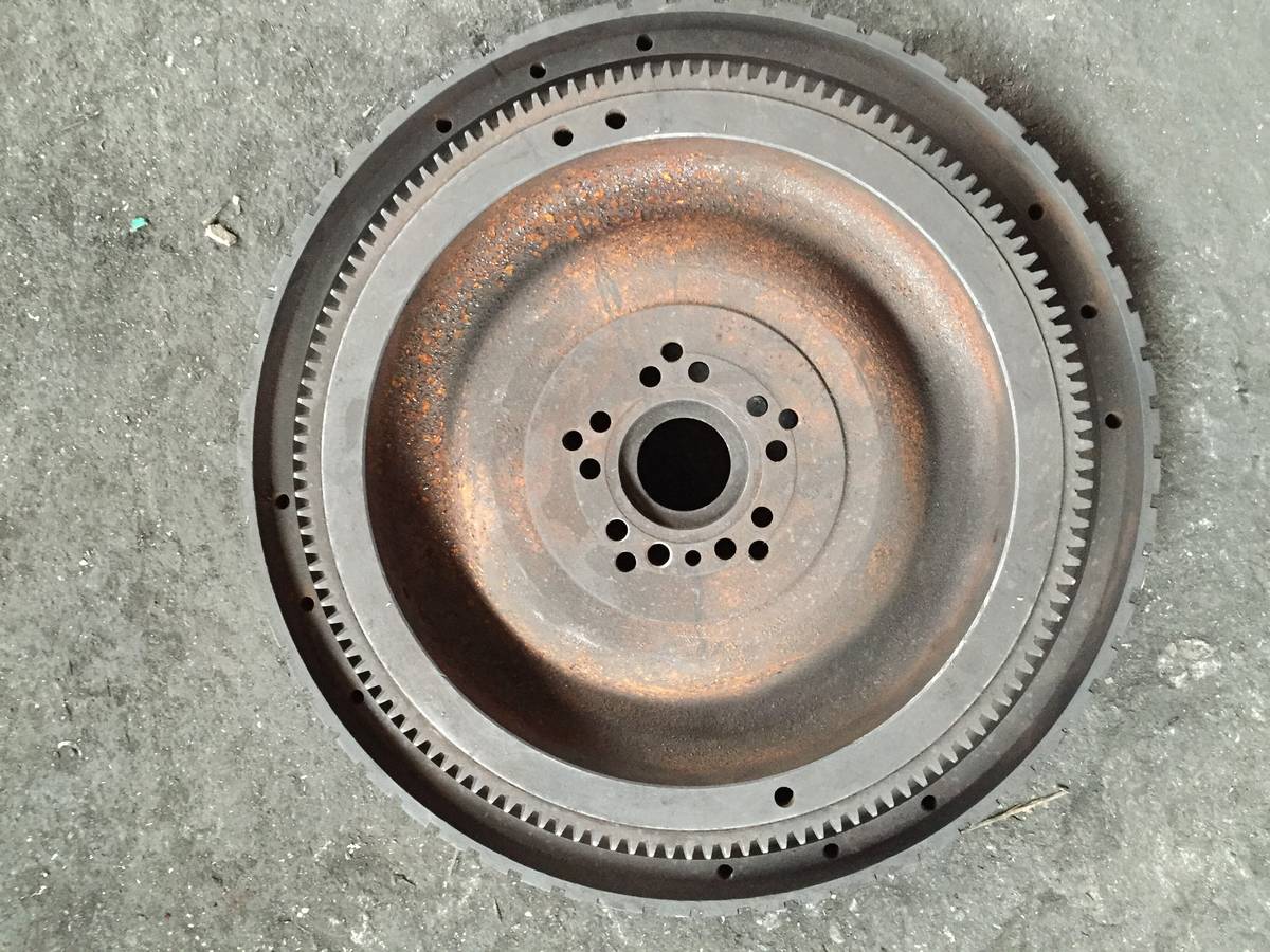
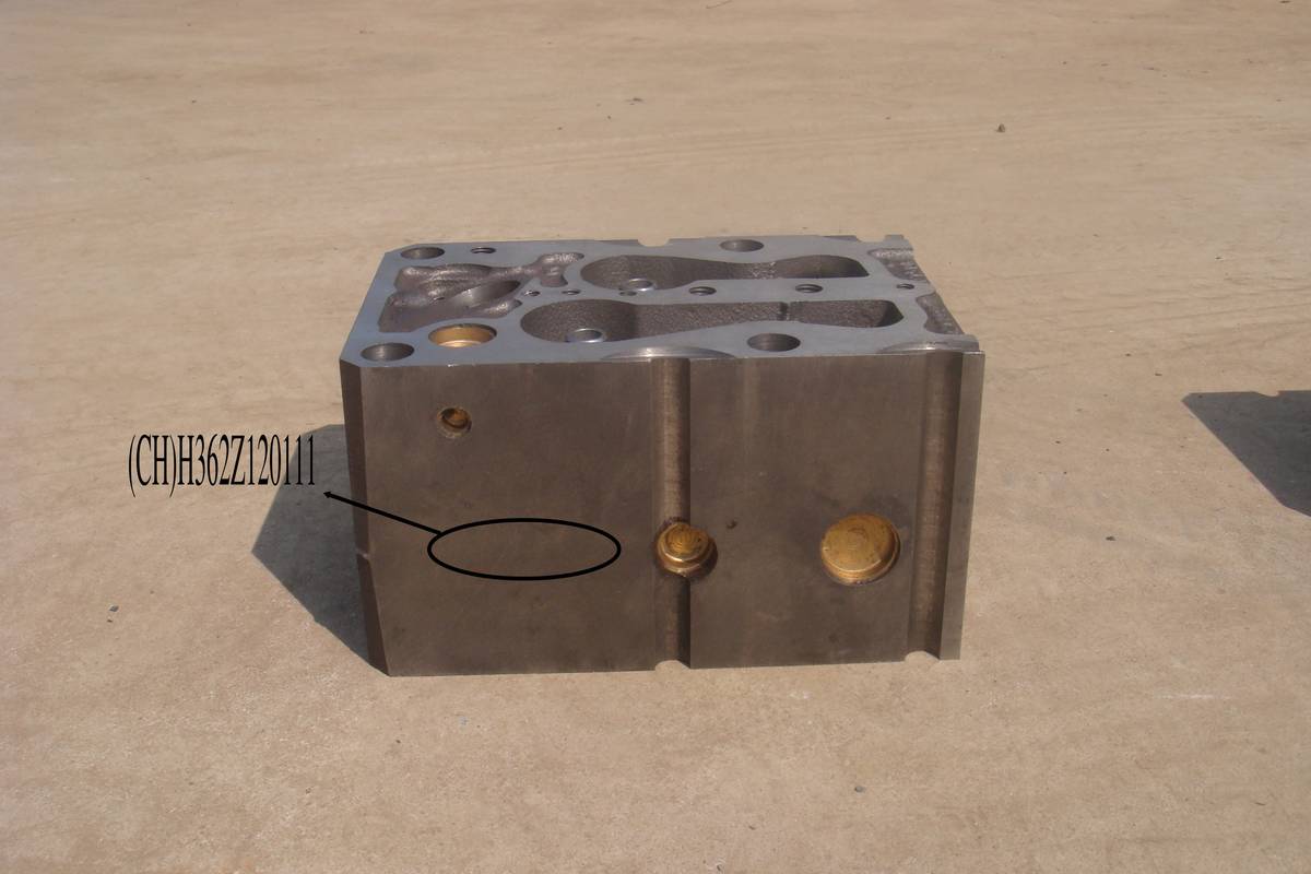
The same sequence applies across our other product lines. These are first article samples of a DEUTZ flywheel and a cylinder head, submitted in the same way:
It is worth being explicit about the sequence we follow, because it is where most schedules are won or lost:
- Drawing review. We read the drawing before we quote, and we come back with questions rather than assumptions.
- DFM feedback. If a callout cannot be held economically at the drawing’s current geometry, we say so before the tool is cut, not after the first batch is scrapped.
- Tooling. Pattern or die manufacture, checked against the drawing, not against the previous job.
- Sample casting. Usually one to three pieces for dimensional and metallurgical checking.
- First article inspection. Every toleranced feature measured, results tabulated against the drawing.
- Customer approval. No mass production starts until the first article is signed off.
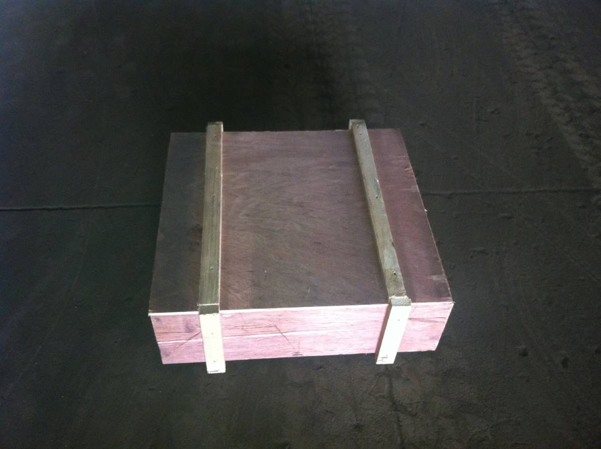
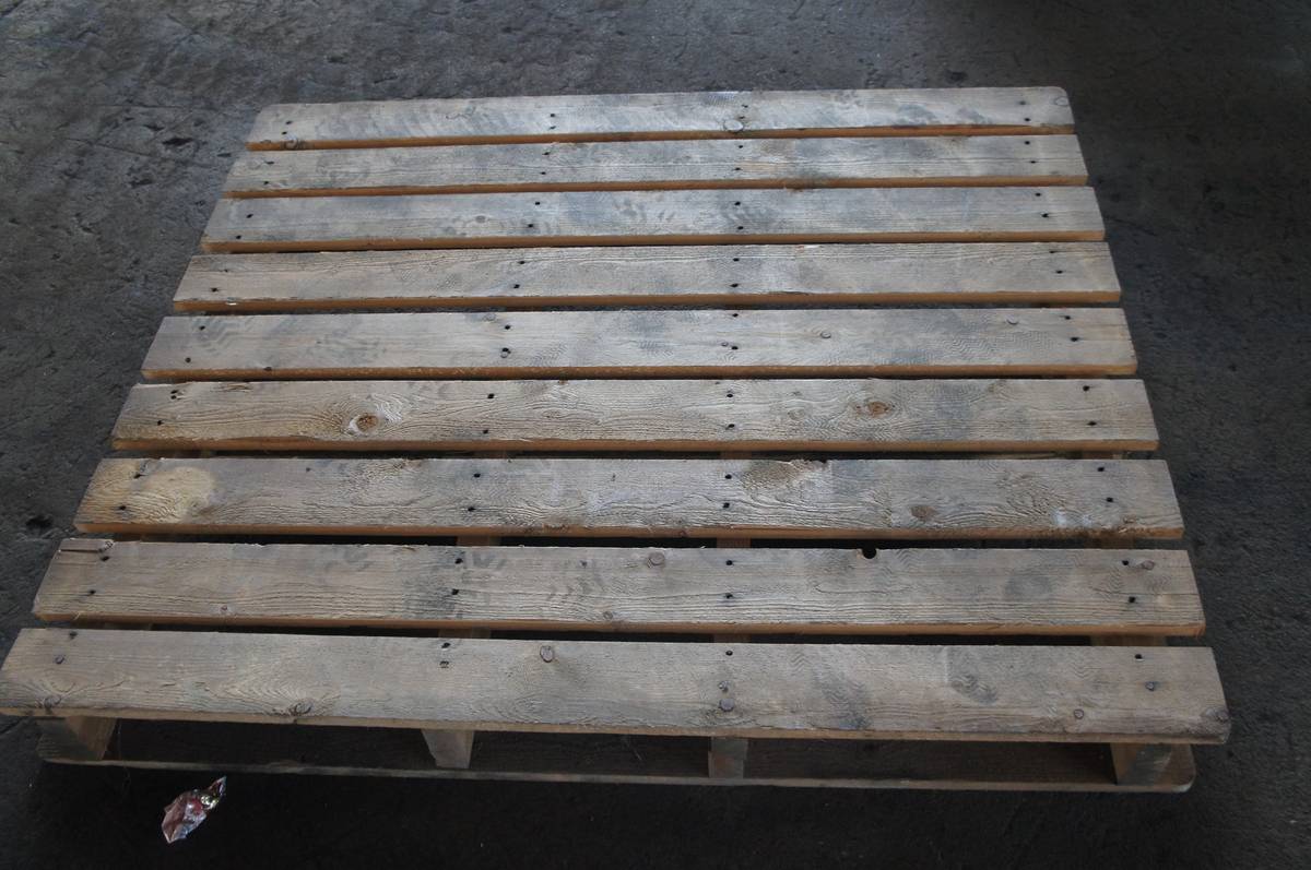
Once approved, the part ships in export packing appropriate to its weight and corrosion sensitivity — sealed crate for heavy castings, palletised and strapped for smaller runs:
What to send us for a quote, and what you get back
We are a foundry in Changyi, Weifang, Shandong, operating to IATF 16949. We cast and machine flywheels, ring gears, flywheel housings, gear housings, cylinder blocks and cylinder heads.
The fastest route to a firm quote is to send us:
- The drawing, in PDF or any readable format. If it is a scanned sheet with faint dimensions, a higher resolution scan is worth the effort.
- Material specification, including any case hardening or surface treatment that follows machining.
- Annual or batch quantity. This decides tooling amortisation and whether we propose a pattern or a die.
- Which features you will machine yourself, and which you need from us. A blank and a fully machined part are very different quotes.
- Your destination port, so we can quote FOB Qingdao.
And here is what you get back, beyond a price: a drawing review with any questions we have, a DFM note on anything that will affect cost or yield, and a first article inspection report against the toleranced features before mass production begins.
If you have a part number, a drawing, a sample, or only photographs of a damaged component, send what you have. We work from all four.
Irene
[email protected]
+86 19953662121
Wangke Industrial Zone, Changyi, Weifang, Shandong, China
FOB Qingdao
Summary
- “Machined blank” means the part is finished everywhere the gear cutter will use as a datum — the teeth belong to the next operation, and the datum quality belongs to the foundry
- The three decisive dimensions on this drawing are OD Ø143.95, ID Ø119.0 and thickness 29.15 mm, each at ±0.04 mm — roughly 0.0016 inches, well beyond caliper control
- The bore is both the cutting datum and the interference fit surface, so cylindricity is worth controlling to half the diameter tolerance even when the drawing does not ask
- The 0.08 mm flatness callout matches published flywheel assembly specifications, and it governs seating, runout and vibration
- SAE 1010 chemistry is declared as a narrow carbon band with capped phosphorus and sulfur — ask for the heat number and mill certificate
- The chamfer note reads as a 0.20 mm maximum, not a target, and it exists to control burrs at a locating edge
- A drawing is a promise and a first article is proof — drawing review, DFM feedback, tooling, sample, inspection and approval come before volume production