
Flywheel Inspection Gauges: When 0.02 mm Is Not Enough
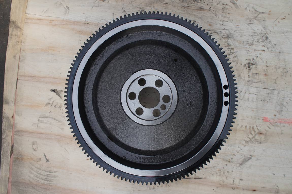
A machined blank we run for an overseas starter gear customer carries plus or minus 0.04 mm on two diameters and on the thickness. The caliper on our bench reads to 0.02 mm. Both numbers are ordinary, and together they explain a large share of the arguments between a buyer and a foundry.
0.02 is half of 0.04. That looks like enough. It is not enough, and the reason sits in how an instrument is chosen rather than in the part.
This article is about the tools. It covers which gauge suits which tolerance on a flywheel, why a caliper cannot settle a band that narrow, and what to write into a purchase order so two benches reach the same number.
Table of Contents
- Why the Tolerance Picks the Gauge
- The Gauges on Our Inspection Bench
- The Arithmetic Behind 0.02 mm
- Three Readings That Pass on the Bench and Fail on the Truck
- Where Each Reading Is Taken
- Temperature and the 20 C Reference
- What to Write in the Purchase Order
- When to Reject and When to Rework
- What Our Bench Cannot Do
- Questions Buyers Ask
- Sources and Evidence Level
Why the Tolerance Picks the Gauge
The working rule in metrology is old and short. The smallest division of the instrument should cut the tolerance band into about ten parts. If the band is 0.08 mm, the instrument should read to 0.008 mm.
Four independent metrology sources state the same rule. Modern Machine Shop gives it twice, once as a rule of thumb and once as basic shop practice. Higher Precision publishes a matching table by tolerance band. RFM metrology names it the ten to one rule and links it to Gage R and R. Evidence level: multi-source.
The rule is a starting point, not a law. Where a tenth cannot be reached, some guides accept 4 to 1 or 5 to 1 and then ask for a measurement system study to prove the reading is still usable. On a flywheel, most dimensions land in the range where the rule can be met.
| Tolerance band | Ten to one asks for | An instrument that meets it | What only looks close |
|---|---|---|---|
| 0.20 mm | 0.02 mm | 0.02 mm caliper | a tape measure |
| 0.08 mm | 0.008 mm | 0.001 mm bore gauge, comparator stand, CMM | 0.02 mm caliper |
| 0.05 mm | 0.005 mm | 0.001 mm test indicator | 0.01 mm micrometer |
| 1.00 mm | 0.10 mm | steel rule | nothing needed |
The second row is the one that matters on a flywheel. A friction face is held to 0.08 mm maximum flatness in the assembly specification we work to. That is an 0.08 mm band, so the rule asks for 0.008 mm.
A 0.02 mm caliper misses that by a factor of 2.5. A 0.01 mm micrometer is closer and still short. Only a 0.001 mm instrument, or a coordinate measuring machine, meets the rule outright.
That is an awkward conclusion for a workshop, and it is the honest one.
The Gauges on Our Inspection Bench
Six instruments cover almost all the dimensional work a flywheel needs. Each photograph below is a tool from our own bench, taken in the packing area.
| Instrument | Graduation | Range marked on the tool | What it is used for |
|---|---|---|---|
| Vernier caliper | 0.02 mm | 0 to 150 mm | hole spacing, quick outside checks, sorting |
| Dial caliper | 0.02 mm | 0 to 300 mm | outside diameter up to 300 mm |
| Outside micrometer | 0.01 mm | 25 to 50 mm | hub height, flange thickness |
| Outside micrometer | 0.01 mm | 100 to 125 mm | ring gear seat and hub diameters |
| Bore dial indicator | 0.01 mm | anvil set marked 18 to 33.5 | pilot bore and bush seats in that range |
| Long vernier caliper | 0.02 mm | 300 mm and above | overall diameter on large parts |
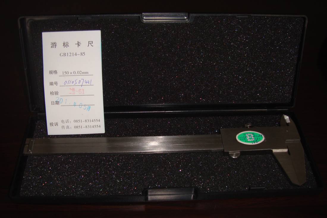
The caliper above is the most used tool on the bench and the least able to settle a tolerance. Its card names the standard as GB 1214 and the range as 150 by 0.02 mm. Everything it is good at is a comparison. Everything it is bad at is a verdict.
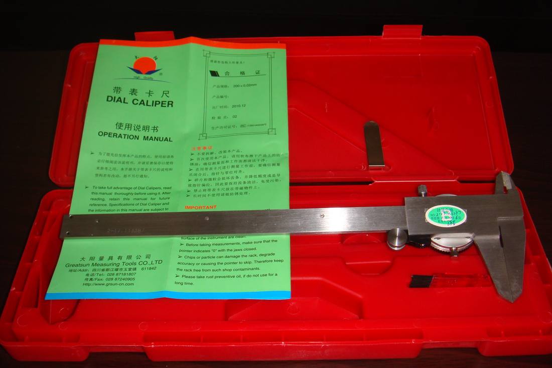
The dial version adds a needle, which makes a trend easier to read. It does not add resolution. The graduation is still 0.02 mm.
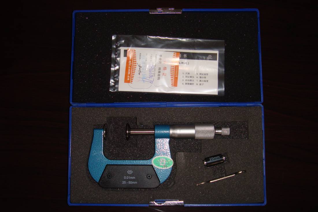
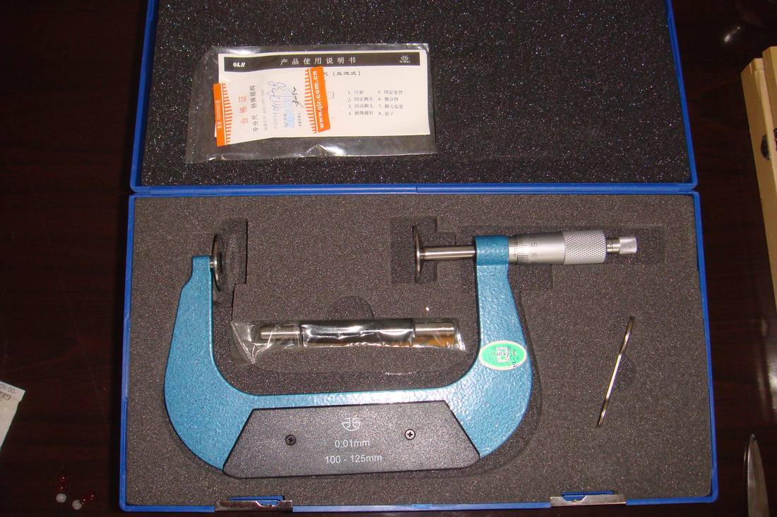
The two micrometers are the tools we trust for thickness and hub height. They read to 0.01 mm, they have a friction thimble that sets the measuring force, and they measure a two point size properly.
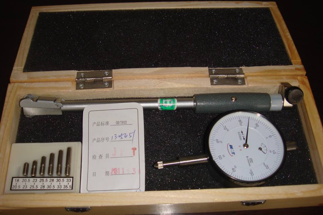
The bore gauge is the only instrument on the bench built for an inside diameter. The card in the box names GB/T 8122, the standard for bore dial indicators. Its anvil set covers the small bores on a flywheel, not the main centre bore.
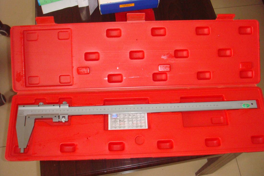
The long caliper reaches across a flywheel that no 150 mm tool will span. It is a layout and sorting tool. On a part 430 mm across, hand pressure alone moves the reading.
Read the Table Against the Rule
Put the graduations beside the rule and the result is uncomfortable. Not one instrument on this bench meets ten to one for an 0.08 mm band. The micrometers and the bore gauge reach eight counts across that band. That is 8 to 1.
That is the honest limit of a workshop bench, and it is worth saying out loud. A supplier who claims a caliper settles a four hundredths callout is describing a wish, not a method.
The Arithmetic Behind 0.02 mm
Take a bore at 119.00 mm with a tolerance of plus or minus 0.04 mm. The limits are 118.96 and 119.04. The band is 0.08 mm wide.
The caliper divides that band into four steps. It can display 118.96, 118.98, 119.00, 119.02 and 119.04. Nothing in between.
Now put a part in it. A bore of 119.045 mm is out of tolerance by 0.005 mm. The caliper rounds it to 119.04 and the part passes. A bore of 118.955 mm is also out, and the caliper rounds it to 118.96, so that part passes as well.
The instrument can hide 0.01 mm at each limit. The whole band is 0.08 mm, so the rounding eats a quarter of the tolerance before anyone reads a number.
| True size | Limit | Caliper shows | Verdict from the caliper |
|---|---|---|---|
| 119.045 | 119.04 | 119.04 | pass, and it should fail |
| 119.035 | 119.04 | 119.04 | pass |
| 118.965 | 118.96 | 118.96 | pass |
| 118.955 | 118.96 | 118.96 | pass, and it should fail |
Round numbers are convenient to argue about and bad to inspect with.
The Second Problem Is Not Resolution
A caliper touches the part on a line at each jaw. The operator sets the force by hand. Any tilt of the jaws against the bore axis adds a cosine error, and the error only grows as the jaws open.
A micrometer replaces the hand with a friction thimble. A bore gauge replaces the two point contact with a self centring bridge, which the standard requires and the photograph above shows. Both changes remove operator judgement from the reading.
That is why a 0.01 mm micrometer and a 0.02 mm caliper are not two versions of the same tool. They answer different questions.
Three Readings That Pass on the Bench and Fail on the Truck
Most comebacks we see are not wrong parts. They are right parts measured the wrong way. Three cases cover most of them.
A Bore Measured With Two Jaws
A caliper measures the distance between two points. A bore is a circle. When the bore is oval, the caliper reports a diameter along one axis and misses the other one.
A three lobe bore is worse. Two jaws can read a perfect size on a shape that no shaft will fit. The bore gauge sees it because the centring bridge averages three contact points.
This is also why the bore is the feature most often argued about after a claim. The part leaves with a number on a card and arrives with a different number on another card, and both were taken with a caliper.
Flatness Judged by Eye
A friction face held to 0.08 mm looks flat. It will look flat at 0.3 mm as well, because the eye cannot resolve a gap that thin across a 400 mm disc.
The field method is a straight edge and a feeler gauge, checked in at least three angular positions. The better method is a surface plate, three support points and a dial indicator swept at two or three radii. The second method reports a number. The first reports an argument.
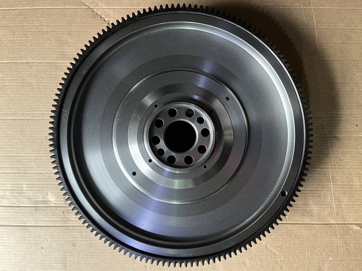
On the part above, the friction ring and the bolt flange are two different heights, and only the ring is the friction face. Sweeping the whole face with one indicator reading blends the two and produces a number that means nothing.
Runout Taken Off the Cast Face
Runout is read with a dial indicator while the part turns. Where the stylus sits decides what the number means.
Put the stylus on the cast back face and the reading includes every unevenness of a surface that was never machined. That is not runout. It is the roughness of a casting.
Put the stylus on the friction face and rotate the part on its bore or on the crank flange. Now the reading describes the part. Rotate it on the crankshaft and the reading describes the crank flange plus the part, which is what the engine sees but not what the drawing limits.
A drawing that gives a runout limit always names the datum beside it. Read the two together.
Where Each Reading Is Taken
The features on a flywheel are few. Each one has a datum, an instrument and a source for its limit.
| Feature | Datum | Instrument | Limit comes from | What it decides |
|---|---|---|---|---|
| Friction face flatness | the face itself | straight edge and feeler, or plate and indicator | assembly specification, 0.08 mm | clutch grip and pedal judder |
| Face thickness | opposite machined faces | 0.01 mm micrometer | drawing | how much material is left for resurfacing |
| Centre bore | the bore axis | bore gauge or inside micrometer | drawing | gearbox input shaft and pilot bearing |
| Crank bolt circle | hole centres | caliper over gauge pins | drawing | whether the part bolts to the crank |
| Clutch cover circle | hole centres | caliper over gauge pins | drawing | which pressure plate fits |
| Ring gear teeth | not dimensional | count, marking pen | catalogue | starter mesh and ratio |
| Step height | friction face to bolt flange | depth micrometer or indicator on a plate | drawing | clamp load |
Two rows in that table need a tool this bench does not own in every size. The centre bore on a truck flywheel runs from about 60 mm to 120 mm, and a 0.001 mm bore gauge in that range is a separate purchase from the 18 to 33.5 mm set in the photograph.
Buyers ask for the bore number more often than any other, and it is the one a caliper answers worst.
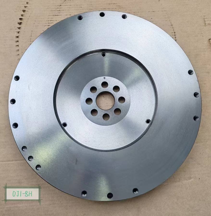
Look at the part above and count the features that need a different instrument. The centre bore needs a bore gauge. The two hole circles need gauge pins and a caliper. The face needs an indicator. The teeth need nothing but a pen and patience.
One part, four tools, and no single reading that stands for the whole.
The 350 mm part above is a good example of a cheap check that catches expensive mistakes. Count the crank holes before anything else. Six holes and eight holes exist on the same 350 mm, 129 tooth body, and the difference is invisible in a listing that quotes only the diameter.
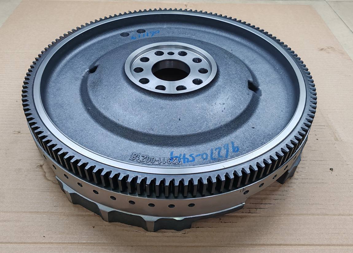
From the side, the two dimensions a caliper handles badly become obvious. The hub height is a micrometer job. The overall diameter across the teeth is a long caliper job, and it is the least useful number on the part.
Temperature and the 20 C Reference
Every dimensional standard assumes a reference temperature. GB/T 8122 sets the inspection room at 20 degrees Celsius plus or minus 5, with the temperature changing by no more than 1 degree per hour during a test. Evidence level: single source, standard summary.
The reason is simple. Grey cast iron expands by roughly 11 parts per million per kelvin, with published ranges from 10.5 to 11.5. Evidence level: multi-source range.
A 400 mm flywheel measured 10 kelvin above the reference is about 0.044 mm larger across the diameter than the same part at 20 C. The band we were arguing about is 0.08 mm. More than half of it came from the thermometer.
| Part size | 10 K above reference | Share of an 0.08 mm band |
|---|---|---|
| 300 mm | 0.033 mm | 41 percent |
| 400 mm | 0.044 mm | 55 percent |
| 480 mm | 0.053 mm | 66 percent |
This is not a theoretical worry. A flywheel that sat in a steel container in the sun, or on a truck bed in winter, is not at 20 C when it is unpacked. Measure it straight away and the number belongs to the weather.
The practical rule is to let the part sit in the inspection area until it stops moving on the indicator. On a heavy casting that takes hours, not minutes.
What to Write in the Purchase Order
A purchase order that names only the part number leaves the measuring method to chance. Five lines close that gap.
- The drawing and its revision. A part number alone does not carry tolerances.
- The datum for every runout and flatness callout. A limit without a datum is not a limit.
- The instrument class, written as a resolution rather than a tool name. Ask for a reading to 0.008 mm, not for a caliper.
- The temperature at which the part will be measured, and by whom.
- The record: which features, how many pieces, and in what form.
The third line is the one that changes behaviour. A supplier who is told to read to 0.008 mm either finds the right instrument or tells you they cannot. Both answers are useful. A supplier who is told to use a caliper will always say yes.
If the order also covers the bolt pattern, the method for that circle is set out in flywheel bolt circle measurement.
When to Reject and When to Rework
Not every out of tolerance reading means scrap. The disposition depends on which feature moved.
| Reading | Disposition | Why |
|---|---|---|
| Face thickness under nominal, flatness still good | rework or accept after review | material can be removed within the resurfacing limit |
| Flatness out, thickness still above minimum | re machine the face | the same cut fixes both |
| Step height changed by a previous cut | re cut to the drawing step | clamp load depends on it |
| Centre bore oversize or out of round | scrap | the bore is the datum and the bearing seat |
| Crank or clutch hole circle wrong | scrap | the pattern is cast and drilled once |
| Cracks between bolt holes or heat cracks on the face | scrap | no machining removes a crack |
| Wrong tooth count | wrong part, not a defect | return it, do not rework it |
The first three rows are the reason a resurfacing limit exists. Removing material from a friction face is normal maintenance, and the limit is what stops maintenance from turning into scrap. The numbers behind that limit are in flywheel resurfacing limits.
What Our Bench Cannot Do
It is easier to trust a supplier who states the limits of the bench, so here are ours.
A CMM report is not something we supply. We cannot issue a roundness or cylindricity figure below 0.01 mm, because the bench instruments do not resolve that fine. Hardness and chemistry are not bench measurements either. When a buyer needs them, they come from the foundry laboratory records.
What we can do is narrower and more useful. We measure outside diameters and thicknesses with a 0.01 mm micrometer. We measure bores in the range the anvil set covers. We read face runout with a dial indicator on a stand. We check hole circles with gauge pins. We photograph what we measured.
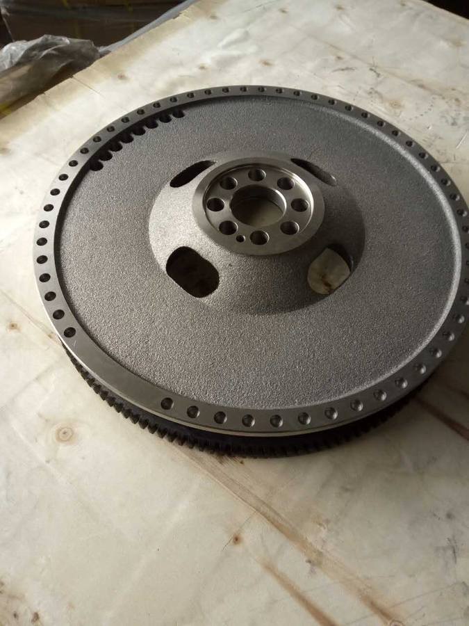
The back of the part above is a good reminder of why a bench has limits. The cast windows and the web are not machined, and no dimensional report describes them. A part can pass every number on the card and still be the wrong casting.
Questions Buyers Ask
Can a caliper measure a flywheel bore
It can produce a number and the number can be wrong. A caliper reads two opposite points, so it misses ovality and cannot see a three lobe shape. Use a bore gauge with a centring bridge, or an inside micrometer read in two directions.
What resolution do I need for a plus or minus 0.04 callout
The band is 0.08 mm, and ten to one asks for 0.008 mm. A 0.001 mm bore gauge or a CMM meets that. A 0.01 mm micrometer gets to eight counts across the band and is the usual workshop compromise, provided both sides use the same tool.
Why do two inspectors disagree about the same flywheel
Three usual causes, in order. A different datum, so the reading describes a different surface. A different temperature, which moves a 400 mm part by about 0.004 mm per kelvin. A different instrument class, where one side is reading a rounding error.
Is a 0.02 mm caliper useless then
No. It is the right tool for hole spacing, for sorting a batch, and for deciding whether a part is worth measuring properly. It is the wrong tool for signing off a tolerance band that is itself 0.08 mm wide.
Do you send inspection records with the parts
We send a dimensional record for the features named on the drawing, taken with the instruments described above. We do not send CMM reports, because our inspection of these parts is bench inspection, and we will not print a number we cannot reproduce.
Does a tighter instrument guarantee a better part
No. It guarantees a better argument. The part is made by the process, and the instrument only decides whether the process is visible.
Sources and Evidence Level
| Claim | Source | Level |
|---|---|---|
| Instrument resolution should be about one tenth of the tolerance band | Modern Machine Shop, two columns; Higher Precision; RFM metrology | multi-source |
| 4 to 1 or 5 to 1 is accepted where a tenth cannot be reached, with a measurement system study | Higher Precision; Modern Machine Shop | dual source |
| Gage R and R acceptance at 10 percent of tolerance, conditional to 30 percent | RFM metrology | single source |
| Bore dial indicators are graded at 0.01 mm and 0.001 mm, range 6 to 1000 mm | GB/T 8122-2024 summaries | dual source |
| Inspection room at 20 plus or minus 5 C, drift under 1 K per hour | GB/T 8122-2024 summary | single source |
| Grey cast iron expands about 10.5 to 11.5 parts per million per kelvin | three foundry and engineering references | multi-source range |
| Friction face flatness limited to 0.08 mm | assembly specification used in our own work | single source |
| Instrument graduations and ranges in the table | the tools in our own photographs | primary, first hand |
Two honesty notes. The tool photographs are ours and show the graduations, but a photograph cannot prove a calibration date. And the thermal figures are arithmetic on a published range, not a measurement of any specific part.
Send the Drawing and the Numbers
If a tolerance is in dispute, send three things: the drawing revision, the datum you are measuring from, and the instrument you used. With those, most disagreements resolve in one exchange.
Browse the range on the product overview, compare weights against the flywheel weight table, or send your drawing to the quotation desk.
We reply with the dimensions we can hold, the instrument we will use to prove them, and the points we still need to confirm. Where a figure comes from one document only, we say so.