
Casting Tolerances and Machining Allowance: What a Cast Iron Part Can Actually Hold
Casting Tolerances and Machining Allowance: What a Cast Iron Part Can Actually Hold
A buyer sends a drawing with one number circled: the machined bore at ±0.04 mm. The same drawing shows the as-cast outside diameter with no tolerance at all, or worse, with a tolerance copied from the machined dimension. Then the first sample arrives, the bore is off, and the conversation turns into an argument about who is responsible.
The argument almost always has the same root cause. Casting tolerance and machining tolerance are not the same quantity, they are not measured the same way, and they differ by roughly an order of magnitude. Once that is clear, the rest of the discussion becomes engineering instead of blame.
This article lays out how casting tolerances are specified, what a foundry can realistically hold, and how machining allowance is sized so that the machined features still land inside their own tolerances regardless of where the casting came out.
Table of Contents
- Two tolerances, two different worlds
- How casting tolerance is specified: the ISO 8062-3 degree system
- Reading the degree tables correctly
- What grade can a foundry actually hold
- Machining allowance: two jobs, one number
- Why allowance is sized on the largest dimension
- Cast iron specifics that change the answer
- How to write it on the drawing
Two tolerances, two different worlds
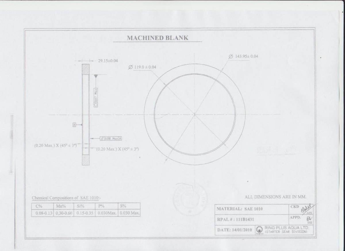
Take a RING PLUS AQUA starter ring gear drawing from a real customer project. The inside bore is called out at 119.0 mm ±0.04 mm. The outside diameter is 143.95 mm ±0.04 mm. Those are machining tolerances and they are entirely normal for a turned part.
Now put that next to an as-cast dimension. Under ISO 8062-3, a grey iron casting in the size range 100 to 160 mm at casting tolerance grade DCTG 10 carries a total tolerance band of 2.8 mm. Not ±2.8 mm. The whole band is 2.8 mm, so if it is applied symmetrically that is ±1.4 mm.
Sit those two numbers side by side and the whole dispute explains itself. The machined bore is held to a band of 0.08 mm. The as-cast outside diameter is held to a band of 2.8 mm. That is a factor of thirty-five. Nobody is being careless. They are different processes answering different questions.
How casting tolerance is specified: the ISO 8062-3 degree system
ISO 8062-3 is the governing standard for dimensional and geometrical tolerances of castings. It does not hand you a single number. It hands you a system.
Dimensional casting tolerances are graded DCTG 1 through DCTG 16. The number is a grade, not a measurement. Grade 1 is the tightest and in practice is reserved for special processes. Grade 16 is the loosest. Ordinary sand casting lives well in the middle of that range.
Geometrical casting tolerances are graded GCTG 2 through GCTG 8, covering straightness, flatness, roundness and the rest. These are separate from the dimensional grades because a part can be dimensionally correct and still be out of round.
Machining allowance is graded RMA A through RMA K, and this is where most drawings go wrong, which is the subject of a later section.
The key structural point is that a casting tolerance is quoted as a band width. When you see DCTG 10 in the 100 to 160 mm size range, the standard value is 2.8 mm of total band. The drawing can apply it symmetrically or asymmetrically, but the total width is what the standard fixes. If you write ±0.04 mm on a casting dimension you have not specified a casting tolerance, you have specified something no sand casting process can deliver, and the foundry will either quote it as a machining operation or quote it with a note that it cannot be met.
Reading the degree tables correctly
Three mistakes account for most of the confusion in tolerance discussions.
The first is treating the table number as a plus-minus value. It is not. A DCTG 8 casting in the 25 to 40 mm range has a band of 1.3 mm. DCTG 12 in the same size range has a band of 5.0 mm. Divide by two before you write a symmetric tolerance, and remember that the standard permits unequal distribution, so the foundry may legitimately hold +0.9 and −0.4 on a 1.3 mm band if the drawing allows it.
The second mistake is quoting a grade without quoting the size range. Tolerance bands widen as the dimension grows. DCTG 8 on a 25 mm feature and DCTG 8 on a 400 mm feature are not the same allowance in millimetres. A grade number only means something when paired with the size band it applies to. This is why a drawing note that reads “casting tolerance DCTG 8” with no size reference is incomplete.
The third mistake is ignoring wall thickness. In ISO 8062-3 the tolerances on wall thickness and on dimensions between two as-cast surfaces are tighter than the general tolerances on overall size, and the standard treats them separately. This matters for housings and covers, where a thin wall that drifts out of tolerance creates a leak path or a stiffness problem that the overall dimension check will never catch.
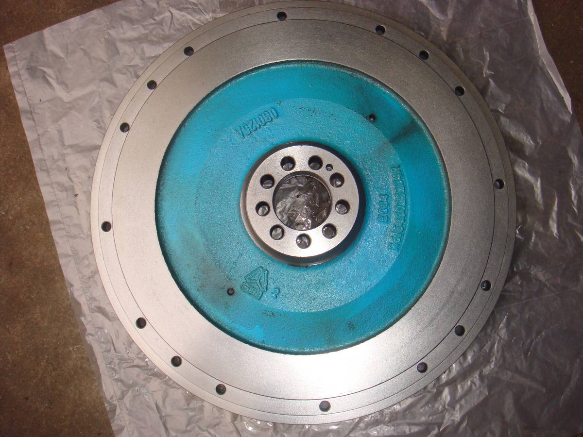
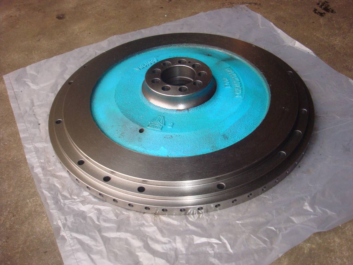
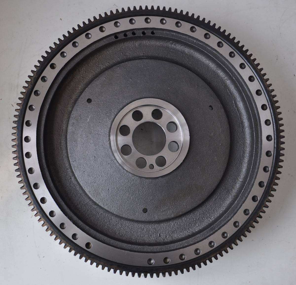
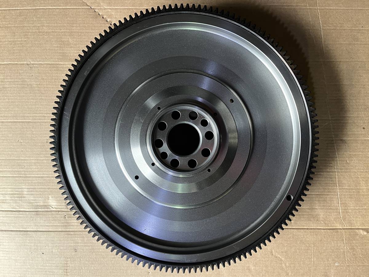
Here is a real machined flywheel face, to keep the target in view. This is what the casting has to be able to become:
What grade can a foundry actually hold
This is where published tables and shop floor reality separate, and the separation is worth understanding because it is the source of most over-specified drawings.
ISO 8062-3 Annex A is informative, not normative. It gives typical achievable grades for various casting processes. For machine moulded grey iron and ductile iron in quantity, that guidance sits around DCTG 8 to DCTG 12 depending on size and complexity.
Process capability data published by foundries and casting suppliers is broadly consistent. For dimensions up to about 200 mm, a well-controlled sand process holds around CT7 to CT8. From 200 to 500 mm, expect CT8 to CT9. Above 500 mm, CT9 to CT10 becomes the realistic band. Hand moulding and one-off work sit looser than all of these.
Two cautions apply to every one of those figures. First, they assume a stable process, a well-maintained pattern, and a part geometry that does not fight the metal. A long thin section or an abrupt mass change will hold worse than its size band suggests. Second, achievable is not the same as specified. Telling a foundry that DCTG 8 is achievable in general does not mean it is achievable on your specific part with your specific tooling, and it does not obligate the foundry to guarantee it.
The practical rule is to specify the loosest grade that still allows the machined features to work. Every step tighter costs money, adds inspection, and increases the rejection rate, and if the tightening is not required by function it buys nothing.
Machining allowance: two jobs, one number
Machining allowance is the extra material left on surfaces that will be cut. It is sized to do two jobs, and forgetting either one is how parts end up scrapped at the machining stage.
The first job is to remove the as-cast skin completely. Sand casting leaves a surface layer that is different from the metal underneath. It carries burnt-on sand, oxide scale, and a zone of porosity that is normal for the process. That layer must come off in the first pass. The working rule on the shop floor is that the first cut has to go below the casting surface by at least 1.5 mm across the whole face, not just at the highest point. If the first pass only kisses the high spots and leaves skin in the low spots, the surface will not clean up and the part is lost.
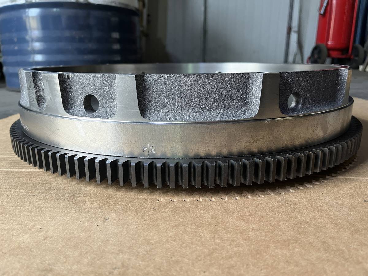
Look at this side view of a 6D22 flywheel. The darker granular band is as-cast surface that was never machined, and the bright band above it is turned surface. They sit on the same part. Getting from one to the other is exactly what allowance is for:
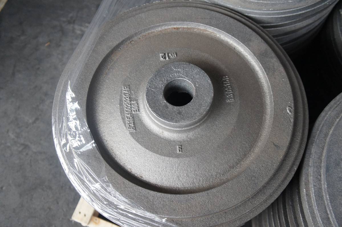
This is the raw blank that becomes a flywheel. Note the bore is still a cast taper, not a machined cylinder, and the face carries cast characters rather than a turned finish:
The second job is to absorb the casting tolerance. The machined feature has to land inside its own tolerance even when the casting comes out at the low end of the band. If the allowance is calculated against the nominal casting dimension, then any casting that comes in undersized will produce an undersized machined feature. The allowance has to be checked against the worst case, which means the lower limit of the casting tolerance band, for any surface where removing too little material is the failure mode.
Counting the allowance is where arithmetic slip-ups happen. A single face that gets machined once takes one allowance. A diameter, or a feature machined from both sides, takes two. A boss that is faced both top and bottom takes two. Getting this wrong by a factor of two will show up immediately in the blank dimension, so it is worth marking each machined surface on the drawing and counting deliberately.
Why allowance is sized on the largest dimension
The machining allowance grade, RMA, is selected from the casting’s overall largest dimension, not from the dimension of the surface being machined. This surprises people, but the logic is sound. The largest dimension drives the pattern size, the amount of metal poured, the cooling behaviour, and the degree to which the whole part distorts. A small boss on a large casting moves more than the same boss on a small casting, because the mass around it moves more.
So a 500 mm diameter flywheel casting and a 100 mm diameter flywheel casting, both at RMA grade H, do not carry the same allowance in millimetres. The large one carries roughly two and a half times the allowance of the small one.
Typical finished allowances for ferrous sand castings, as published by casting suppliers, run along these lines. Small machine moulded parts up to roughly 250 mm: 1.5 to 4 mm per surface. Medium machine moulded parts from 250 to 630 mm: 2.5 to 6 mm per surface. Large machine moulded parts from 630 to 1600 mm: 3.5 to 8 mm. Hand moulded parts in the 250 to 630 mm range: 3.5 to 12 mm. The ranges are wide because they cover different grades within RMA, and the grade is chosen according to how much machining the part needs.
Under ISO 8062-3 Table 12, the 400 to 630 mm size band at RMA grade H specifies 6 mm of allowance. That is a per-surface figure, and it is applied to every machined surface on the part.
Cast iron specifics that change the answer
Cast iron is more forgiving than steel on several of these parameters, and it is worth knowing which way the allowance moves.
Shrinkage for grey iron runs roughly 0.8 to 1.0 percent in the pattern. Ductile iron runs a little higher, around 1.0 to 1.2 percent, because of the graphite expansion behaviour. The patternmaker builds this in, but it means the casting tolerance and the shrinkage allowance interact. If the pattern was made for one iron grade and the pour comes out as another, the dimensions drift.
Minimum wall thickness is a real constraint. For grey iron in green sand, 4 to 6 mm is the practical floor. Ductile iron needs 5 to 7 mm. Below that, the metal does not fill reliably and the casting is not sound. So a wall thickness tolerance that implies a 3 mm wall is not a tolerance question, it is a design question.
Draft angle is required, not optional. Roughly 1.0 to 1.5 degrees on external surfaces and 1.5 to 2.0 degrees on internal surfaces for green sand. A vertical wall with zero draft will not come out of the mould cleanly, and the damage shows up as a dimensional error on the cast surface. If the drawing shows a vertical as-cast wall with a tight tolerance, the foundry cannot honour both.
Surface finish and tolerance travel together. As-cast surfaces on sand castings typically land around Ra 6.3 to 12.5 micrometres. A machined face typically lands around Ra 3.2 to 6.3 micrometres. If a drawing requires a finish in the machined range on a surface shown as cast, it is really asking for a machining operation, and the allowance has to be there for it.
How to write it on the drawing
The simplest way to remove the argument is to make the two tolerance systems visibly separate on the drawing.
Mark every surface as cast or as machined. A small symbol or a shaded region is enough. Machined dimensions get the machining tolerance. As-cast dimensions get a casting tolerance grade referenced to a size band, or a general note such as “casting tolerances per ISO 8062-3, DCTG 10” with the size bands understood to apply.
Do not copy a machining tolerance onto a casting dimension. It is the single most common error and it guarantees a dispute on the first sample.
Reference the standard with the edition year, because the tables have changed between editions and a supplier working to an older edition will produce different numbers.
State the datum structure for the casting, not just for the finished part. The casting needs its own datums so the dimensional check at the foundry means something, otherwise the part is measured against an arbitrary reference and the result is not comparable to anything.
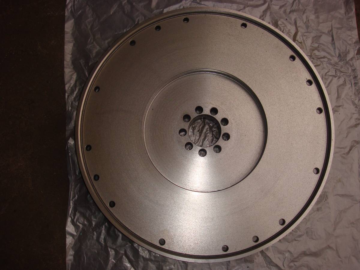
Finally, expect to see a first article report. For a part like this, the dimensional check at the casting stage costs very little compared to discovering the problem after machining. This finished part started as the blank shown above, and both checks matter:
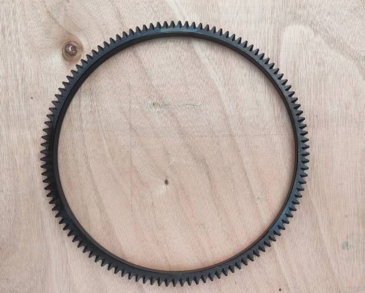
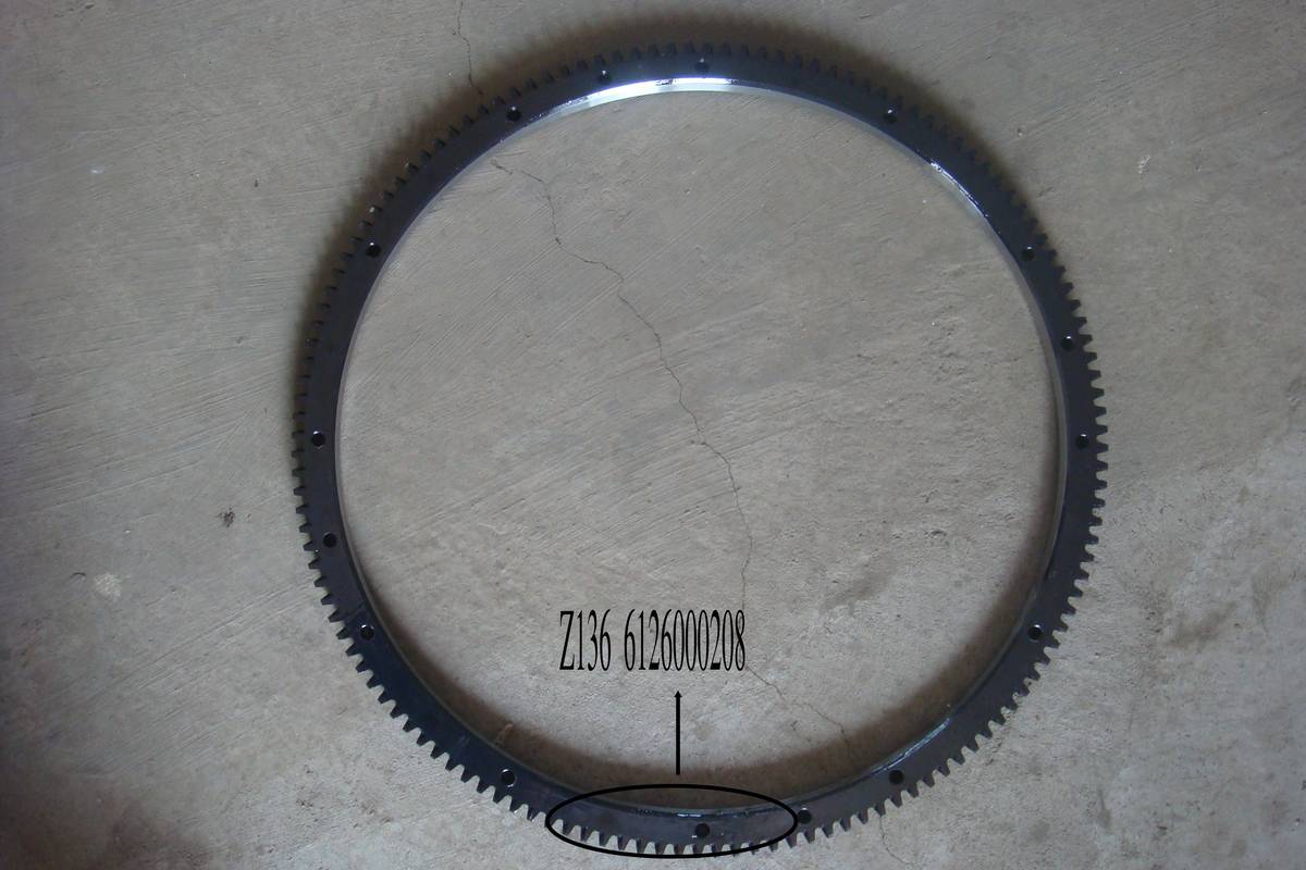
The same discipline applies to ring gears, which are a thin ring casting that has to stay round. The finished export gear and a sample lot:
And for comparison, a customer drawing where the as-cast blank dimensions and the machined bore carry quite different tolerances. The machined bore is the tight number. The blank dimensions are looser on purpose:
A cast part that carries its own marking, which is the foundry’s traceability reference and is itself a cast feature with its own tolerance:
If you are working through a casting specification for a flywheel, ring gear, housing or block and want a second opinion on whether the tolerances and allowances are realistic for sand casting, we can look at the drawing and say so before the tooling is cut. Send the drawing to Irene at [email protected], or call +86 19953662121. We cast and machine at our foundry in Changyi Wangke Industrial Park, Shandong, and ship FOB Qingdao.