
Flywheel and Ring Gear Runout (TIR): How to Measure It and What the Limits Actually Are
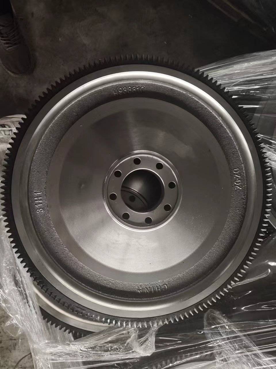
Flywheel and Ring Gear Runout (TIR): How to Measure It and What the Limits Actually Are
A flywheel comes off an assembly line, the truck idles rough, and the owner says the flywheel is “not flat.” Pull it, lay it on a surface plate, sweep it with a dial indicator, and the reading is 0.06 mm. Looks perfect. Put it back on, and it still shakes.
The problem is not that 0.06 mm is wrong. The problem is that it has nothing to do with whether the part will shake once it is bolted to a crankshaft. A surface plate is a surface plate. A crank bore is a crank bore. They are not the same rotation axis.
This article covers three things: what runout actually is, how to measure it correctly, and what the real limits are across different OEM manuals. Every number below is attributed to its source.
Table of Contents
- Three terms that keep getting confused
- How TIR is calculated: a worked example from a manual
- Why “lay it flat on a bench” tells you nothing
- The actual limits: real numbers from real manuals
- Tooling: how you mount the indicator matters more than the indicator
- Out of tolerance: a diagnostic order
- Four things an acceptance sheet has to state
- The short version
Three Terms That Keep Getting Confused
The words that show up on a machining drawing or an inspection sheet look interchangeable. They are not, because they do not measure the same thing.
Flatness is a form error of the surface itself, with no external datum involved. Lay the friction face up on a surface plate and measure the gap between the highest and lowest point — that is flatness. It is a property of the part alone.
Face runout is the maximum variation in readings taken on a face while the part rotates about a specified axis, measured perpendicular to that axis. It requires a rotation axis — and it has to be the axis the part actually spins on in the engine, which is the crankshaft centerline.
Radial runout is the maximum variation in distance from the rotation axis to a cylindrical surface — a ring gear’s tooth tips, a flywheel housing bore. This is what you check after a ring gear has been pressed on.
None of these three can be derived from the others. A flywheel with excellent flatness can exceed face runout limits, because its friction face may not be parallel to the crank mounting face. The reverse is equally true.
TIR (Total Indicator Runout) is simply the method of capturing these values with a dial indicator: the maximum reading minus the minimum reading over one full revolution.
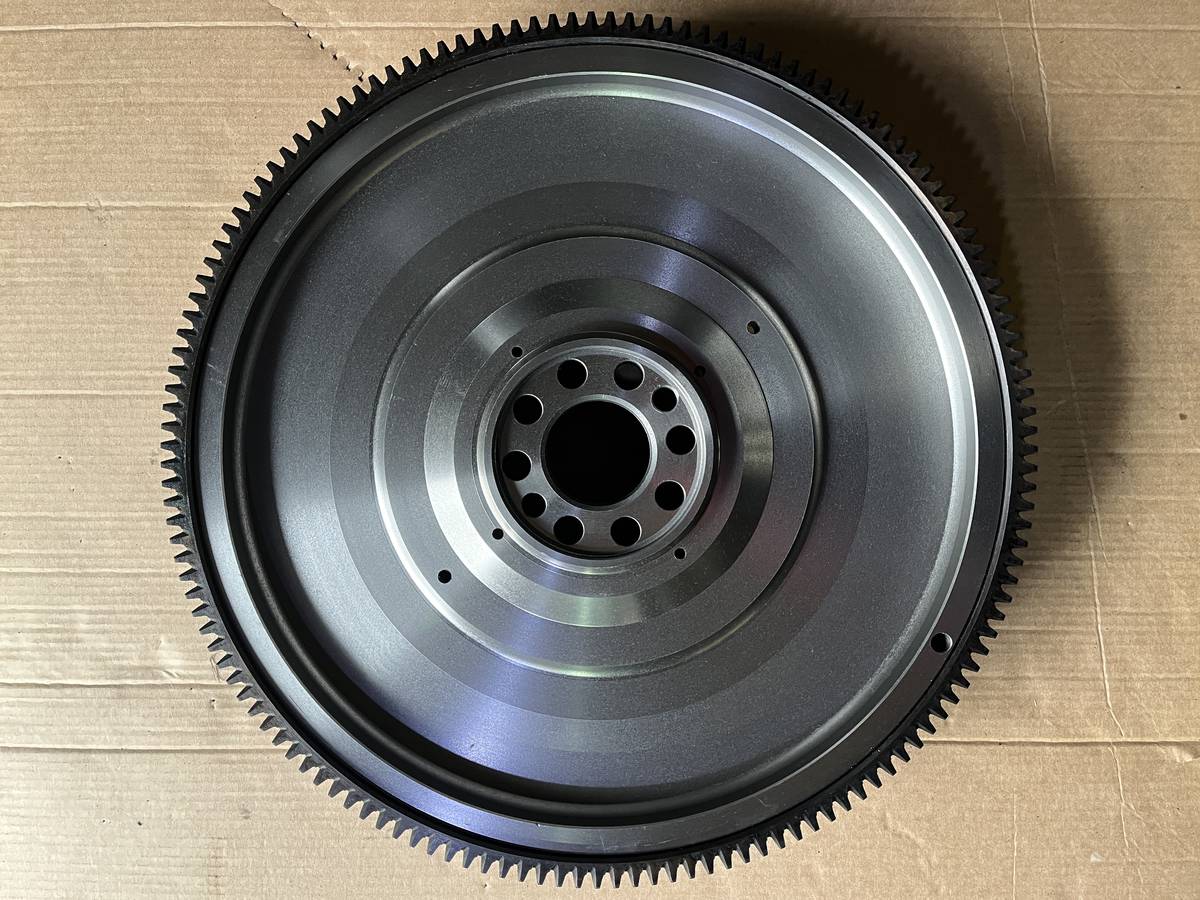
A finished flywheel friction face. A drawing note of “flatness 0.08 Max” describes the shape of this surface. A note of “face runout” describes how it behaves once mounted on a crankshaft. Those are not the same number.
How TIR Is Calculated: A Worked Example from a Manual
TIR is subtraction, which sounds too simple to need explaining. What actually goes wrong is the way the readings are taken.
Cummins publishes a standard example. Put the indicator tip on the flywheel friction face and rotate the crankshaft slowly:
- At 12 o’clock: +0.08 mm
- At 3 o’clock: −0.05 mm
- At 6 o’clock: −0.02 mm
- At 9 o’clock: +0.03 mm
TIR = highest − lowest = +0.08 − (−0.05) = 0.13 mm.
Three things matter here.
First, keep the sign. The indicator needle moves in a direction. If you record absolute values only, your final subtraction is wrong.
Second, the needle must return to zero at the start point. Coming back around to 12 o’clock, the indicator should read the same value it started at. If it does not, the crankshaft moved axially or the indicator base slipped — the measurement is invalid and must be repeated. This is the single most frequently skipped step, and the one that decides whether the number means anything.
Third, readings go at four equally spaced points, or at whatever number of points the drawing specifies. Turning the crank at random and grabbing the biggest number is not reproducible, and a customer receiving your inspection report cannot verify it.
One more detail the manuals repeat: push the crankshaft fully to one side before every reading, to take up the axial clearance. A crankshaft sits in its bearings with end play. If you do not remove it, your runout reading absorbs the end play itself and comes out inflated.
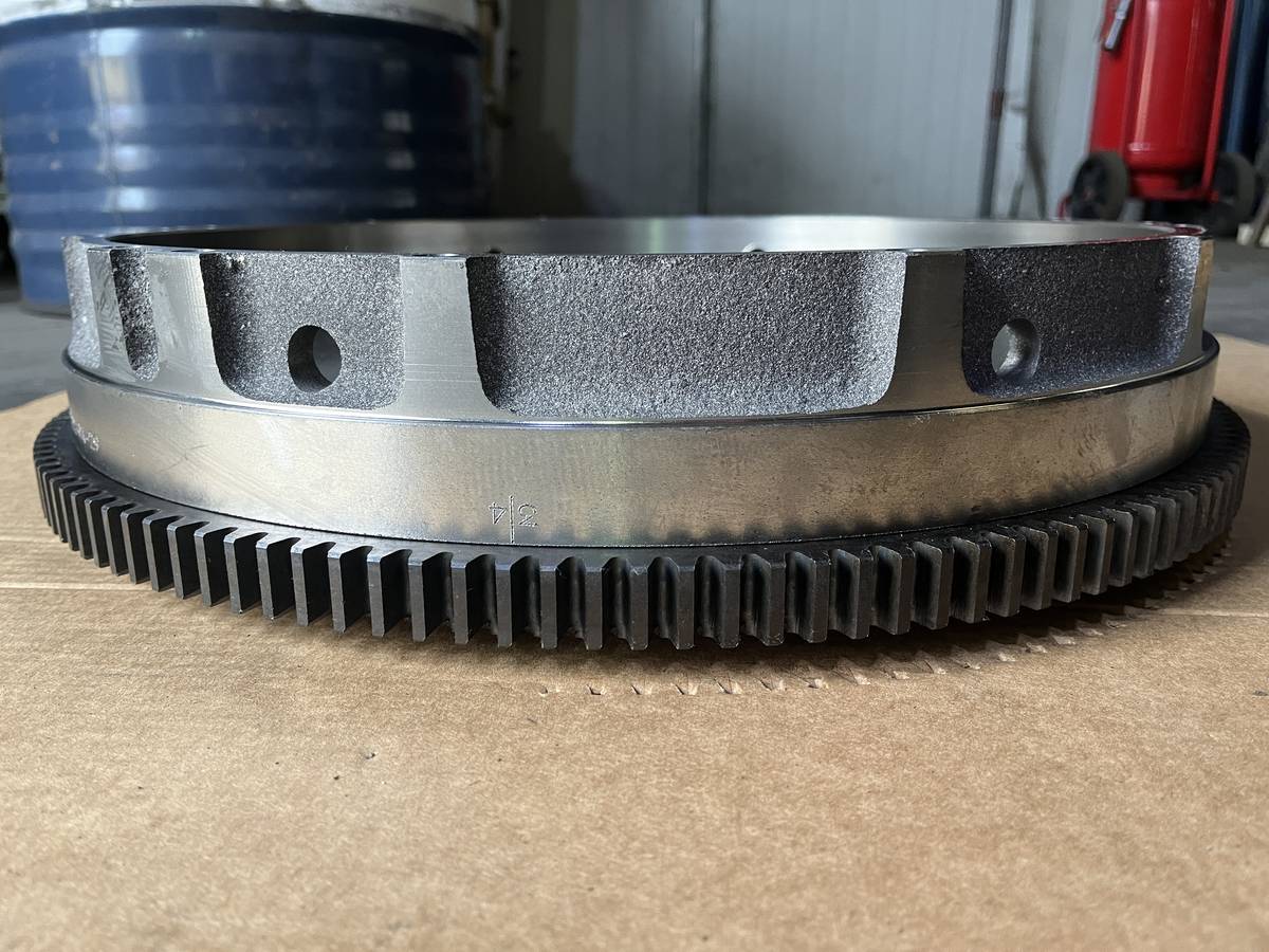
The mounting bore and bolt holes of a flywheel. The datum for a runout measurement is, in effect, the axis defined by these features — and in the engine, that axis is the crankshaft centerline.
Why “Lay It Flat on a Bench” Tells You Nothing
Back to that first flywheel. Lay it on an inspection plate and sweep the friction face. What you measured is:
- the surface plate datum → the flywheel’s mounting face → the friction face
That is the stacked flatness of the whole chain. It answers the question “is this part geometrically sound in itself.” It does not answer “will the friction face wobble once installed.”
Installed, the friction face rotates about the crankshaft centerline. That axis is set by the crank flange spigot and face — not by the flywheel’s own mounting face. If those two are out of parallel by even 0.05 mm, the assembled face runout comes out far larger than the bench number.
So the correct procedure is:
Mount the flywheel to the crankshaft in its actual assembled condition — or to a dedicated inspection fixture that reproduces the crank flange — and rotate the part about the crank bore / flange spigot, sweeping the friction face.
The same applies to ring gears. A ring gear is shrunk onto the flywheel’s outer diameter, so its radial runout has to be measured after it has been installed on the flywheel. Suspending a bare ring gear in the air and sweeping it measures the gear’s own out-of-roundness, which is not the assembled number.
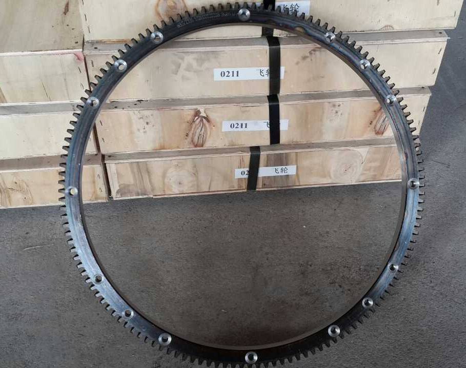
A 136-tooth ring gear. A bearing error in the gear as shipped and the radial runout after installation are two different quantities — runout can only be measured once the gear has been pressed on and has cooled and gripped.
The Actual Limits: Real Numbers from Real Manuals
This is the most useful section of the article and the one requiring the most care. Runout limits are not a single industry-wide value. They depend on the brand, the engine model, the location being measured (flywheel body / flywheel housing / ring gear), and the type of runout (bore / face / radial). Every figure below is attributed.
4.1 Flywheel Housing Bore and Face
Cummins publishes a table giving maximum bore and face runout by SAE housing size. The smaller the SAE number, the larger the housing, and the larger the permitted absolute runout:
| SAE housing | Bore diameter range (mm) | Max runout TIR (mm) |
|---|---|---|
| 00 | 784.15 – 784.65 | 0.48 |
| 0 | 657.45 – 647.95 | 0.41 |
| 1/2 | 584.00 – 584.40 | 0.36 |
| 1 | 510.98 – 511.38 | 0.30 |
| 2 | 447.55 – 447.81 | 0.28 |
| 3 | 409.45 – 409.71 | 0.25 |
The pattern is clear: larger bore, larger absolute tolerance band. This reflects both machining capability and the stiffness of larger housings. Do not carry these values across brands. They are a Cummins published condition; other manufacturers publish their own.
4.2 The Flywheel Body Itself
Cummins N14 manual: flywheel bore runout TIR ≤ 0.127 mm (0.005 in); flywheel face runout is to be measured at four equally spaced points.
The Cummins B Series manual splits it into two line items:
– Flywheel bore alignment TIR ≤ 0.020 mm (0.008 in)
– Flywheel bore runout TIR ≤ 0.127 mm (0.005 in)
7.3L Power Stroke specification: flywheel friction face TIR ≤ 0.203 mm (0.008 in), measured at roughly 25 mm in from the outer edge; ring gear face TIR ≤ 0.56 mm (0.022 in). The manual adds a diagnostic order — check first for burrs or debris between the flywheel and the crank flange.
The Mitsubishi L Series manual gives a flatness figure instead: standard 0.08 mm, limit 0.50 mm.
Notice the layering here. Flywheel bore runout limits typically sit in the 0.02–0.13 mm band, because the bore defines the rotation axis and must be tight. Friction face runout sits in the 0.13–0.25 mm band, because the face is large and thermally loaded, so more is allowed. Treating those two as one number is the most common mistake in this area.
4.3 Ring Gear Installation
The Detroit Diesel MBE Series manuals give a complete set of ring gear parameters:
| Item | MBE 900 | MBE 4000 |
|---|---|---|
| Ring gear to flywheel interference | 0.295 – 0.575 mm | 0.295 – 0.645 mm |
| Ring gear radial runout allowance | 0.5 mm | 0.5 mm |
| Ring gear heating temperature | 250 – 280 °C | 200 – 230 °C |
The Cummins B Series manual specifies an oven preheat of 127 °C (260 °F) for about 20 minutes. The Mitsubishi L Series figure is around 100 °C.
Those three temperatures are very different — 127 °C, 200–230 °C, 250–280 °C. It depends on the interference amount and the cross-sectional stiffness of the gear: more interference and a heavier section need more expansion, hence more heat. This is also why ring gear runout must be measured after installation — heating temperature, cooling rate, and press force each change the final roundness once the gear grips.
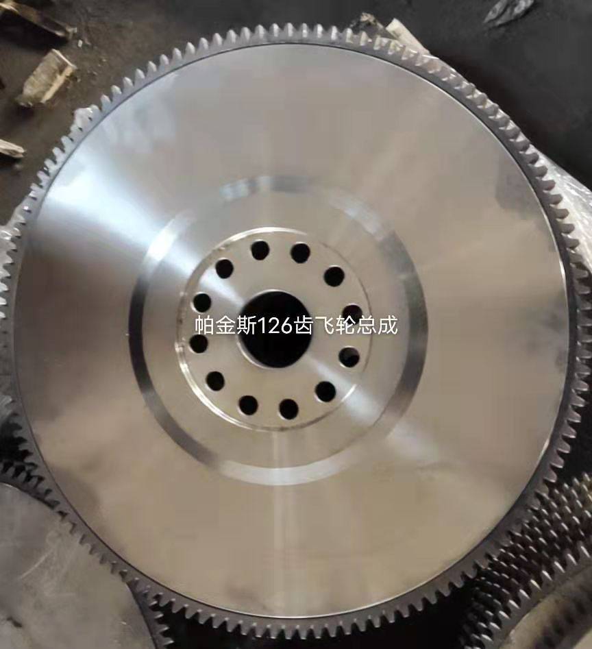
A flywheel assembly with the ring gear already installed (Perkins, 126 teeth). This is the only condition in which ring gear radial runout means anything.
Tooling: How You Mount the Indicator Matters More Than the Indicator
Runout measurement uses a dial indicator on a magnetic base or a dedicated bracket. The requirements are not complicated, but each one is mandatory:
Resolution. The general requirement is 0.001 in (0.01 mm) class. Reading a 0.02 mm limit on a 0.01 mm graduated indicator puts you at the edge of the noise floor — workable but not dependable. Where possible, use a 0.001 mm graduation.
Preload. The contact tip needs some preload against the surface, typically around 0.010 in, roughly a quarter turn. Too little, and small surface waviness makes the tip skip or lift off. Too much, and the stem deflects, biasing every reading high.
Perpendicularity. The tip axis must be perpendicular to the surface being measured. Measured at an angle, the reading is the true value multiplied by the cosine of the tilt — which sounds small, but at a 0.02 mm limit a few degrees of tilt consumes the whole allowance. For radial runout, the tip must point at the center of rotation — radially inward.
Bracket rigidity. The manuals state this outright: if an extension rod is loose, or the indicator slides on its mount, the readings are invalid. After each setup, nudge the bracket and let it spring back — if the needle does not return to the same reading, the mount is floating and must be changed.
Cleanliness. Wipe the flywheel-to-crank flange interface and the spigot before measuring. A 0.05 mm metal chip or a lump of cured paint will push the reading straight past the limit.
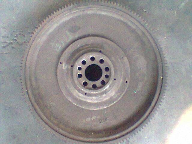
A raw flywheel casting. Between this and a finished part come turning, drilling, and balancing. Runout is largely fixed at the rough machining stage — finish machining only brings it inside the allowance. If the casting itself has localized hard spots from slag or porosity, the tool deflects during finishing.
Out of Tolerance: A Diagnostic Order
A runout value over the limit does not automatically mean the part is scrap. The manuals follow broadly the same sequence:
Step one: check the interface. Look for burrs, debris, impact high spots, old gasket residue, or cured paint between the flywheel and the crank flange, or between the housing and the block. This is the most common repairable cause and accounts for a meaningful share of cases.
Step two: re-measure to confirm. After cleaning, measure again — pushing the crank to the same side before each reading to remove end play, and confirming the needle returns to zero. Many “out of tolerance” results turn out to be a failed measurement.
Step three: measure the crank flange itself. If it is still out after cleaning, remove the flywheel and measure the crank flange face and bore runout directly. If the flange is out, the problem is not the part in your hands. For flywheel housings specifically, US Army TM manuals give a field technique: tap the high side with a soft mallet to bring back half the runout. That applies to housings, which are stiff — not to the flywheel body.
Step four: only now judge replacement. If the flange is good, the interface is clean, and the bolts were torqued correctly (Cummins N14 specifies 271 N·m / 200 ft-lb, tightened in a star pattern in stages), and the flywheel itself is still out of tolerance — then it is the part.
Torque and sequence deserve their own emphasis. Tighten flywheel bolts in the wrong order, or unevenly, and you will distort a good flywheel into a bad one. Star-pattern (diagonal cross) tightening in stages, finishing at the manual’s specified torque, is not optional.
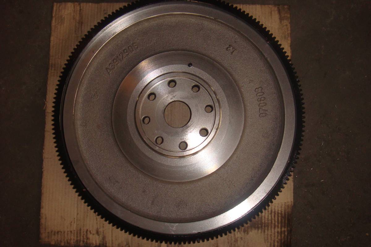
The web of a Cummins flywheel, with A3912906 cast into it. Cast-in numbers like this are used at assembly and inspection to confirm the revision. Confirming the number matches before you replace a flywheel is far cheaper than chasing a runout problem afterward.
The friction face of a Cummins 158-tooth flywheel. For face runout, the indicator contact point is normally placed on the friction face near the outer edge at mid-radius, with the exact location set by the drawing — different contact radii give different readings, so an inspection report must state where the contact point was.
Four Things an Acceptance Sheet Has to State
If you are sending runout requirements to a supplier, or submitting an inspection report to a customer, leaving out any of these four makes the data unverifiable:
- Location and type — flywheel friction face runout, or flywheel housing bore radial runout, or ring gear radial runout. State it.
- Rotation datum — crankshaft centerline, or a dedicated inspection fixture spigot, or (for a ring gear) the flywheel after installation. Without this, the number has no interpretive value.
- Contact radius — for face runout, the contact radius directly affects the reading; for radial runout, the axial position of the contact does the same. State it.
- Limit and basis — enter “0.13 mm” and cite the source (customer drawing / OEM manual and revision). Never a bare number.
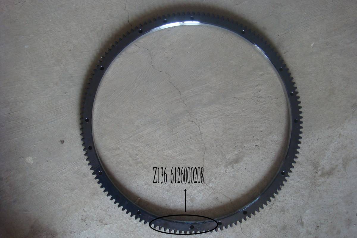
A ring gear marked Z136. Tooth count, outer diameter, runout limit, and heating temperature on a drawing form one complete parameter set. Pulling any single item out of that set makes it meaningless.
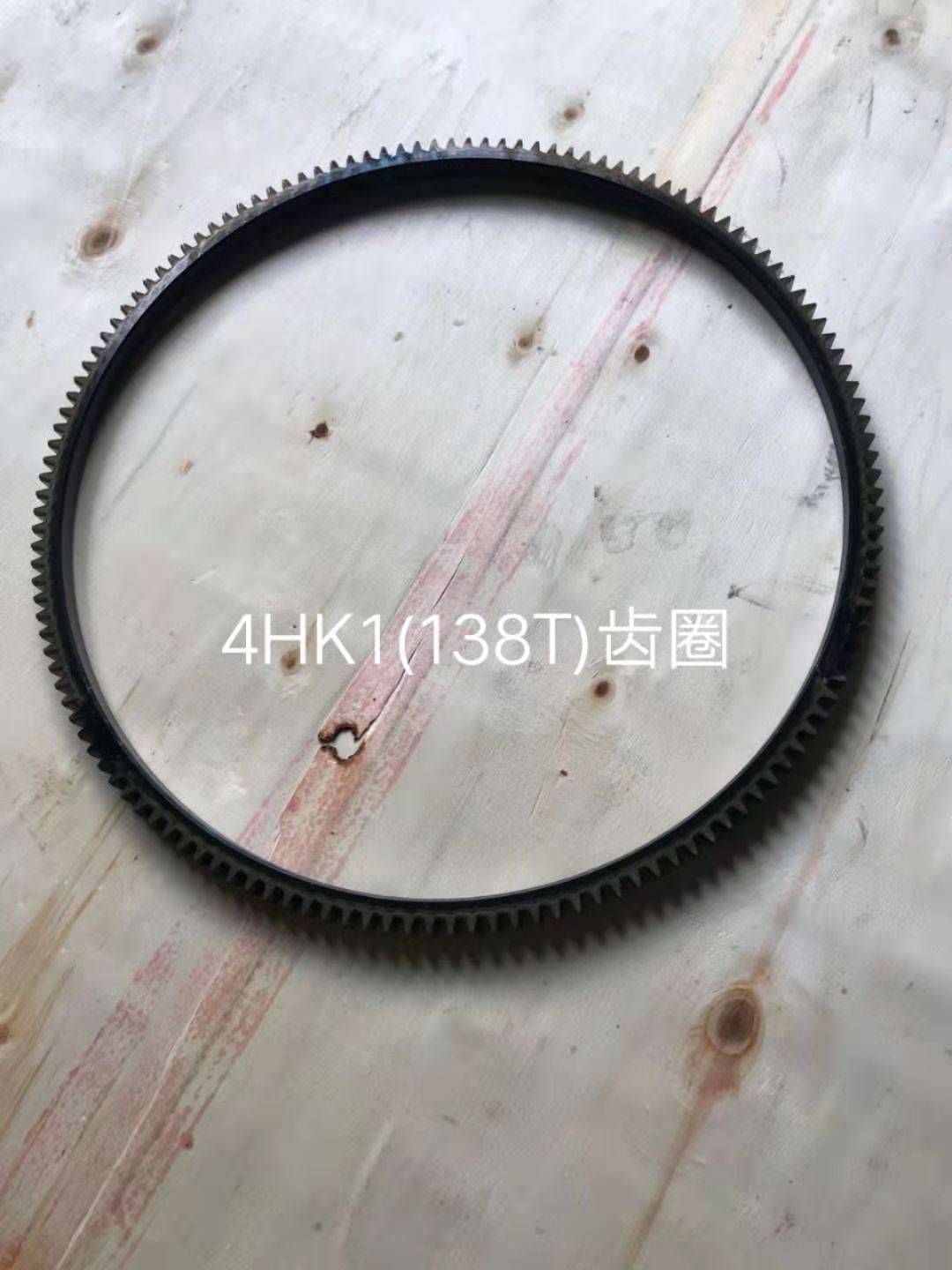
An ISUZU 4HK1 ring gear, 138 teeth. Different versions of the same engine family can take different tooth counts — confirm the tooth count before discussing runout.
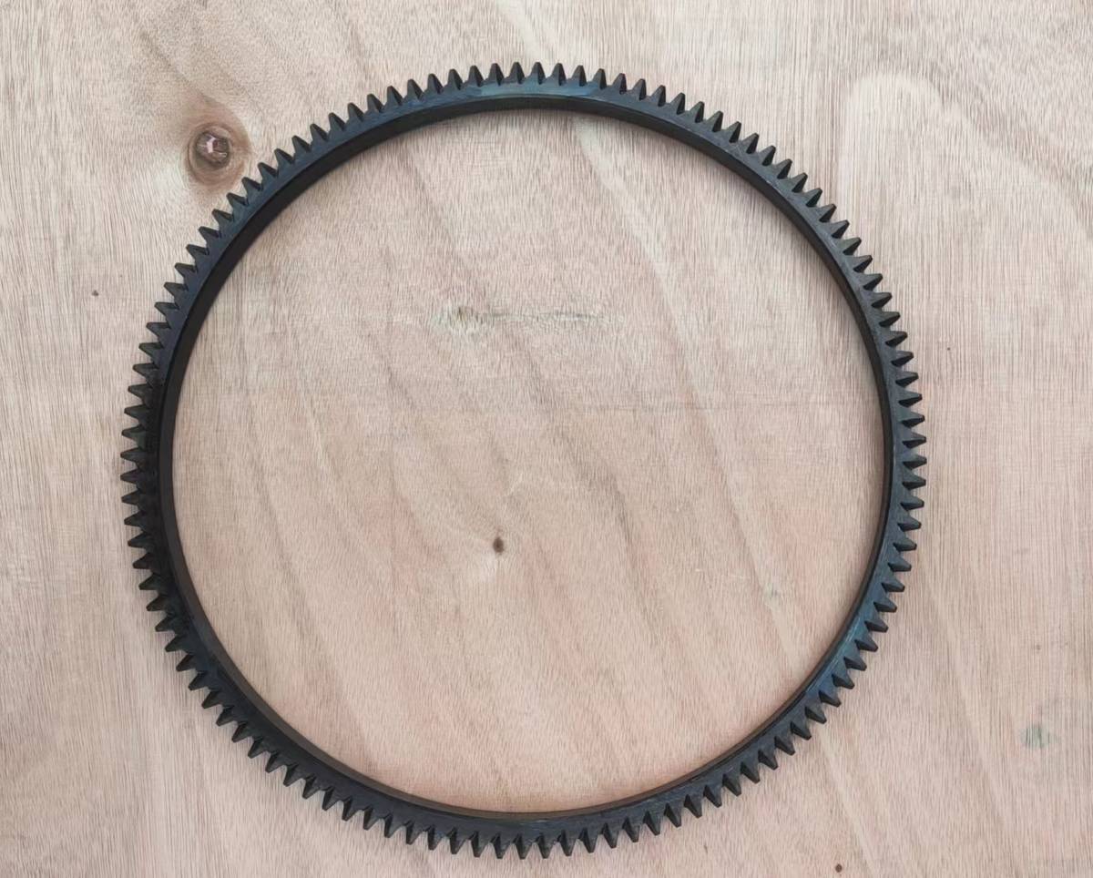
A coarse-pitch ring gear for an export order. Coarse pitch gives higher tooth root strength and more tolerance for starter pinion engagement, but cumulative pitch error has a larger effect on radial runout — so acceptance requirements are usually tighter than for fine pitch.
The Short Version
Flatness is a property of the part. Runout is how the part behaves once it is on a crankshaft. The first can be measured on a bench. The second has to be measured about the crank bore as the rotation axis, with the part turning — pushing the crank to the same side before every reading, and confirming the needle returns to zero.
On limits, the useful takeaway is the layering: flywheel bore runout is usually tightest (0.02–0.13 mm), friction face runout next (0.13–0.25 mm), installed ring gear radial runout loosest (around 0.5 mm), and flywheel housing bore and face runout by SAE size (0.25–0.48 mm). For specifics, always go to the customer drawing and the applicable OEM manual — everything quoted here is a published manufacturer condition, not a cross-brand universal specification.
About Us
Changwei Intelligent Equipment (Changchai Power) is an IATF 16949 certified iron casting facility in the Wangke Industrial Zone, Changyi, Weifang, Shandong, China. We produce flywheels, ring gears, flywheel housings, timing gear housings, cylinder blocks and heads, and transmission housings in grey and ductile iron. We build to drawing, and we also take samples and drawings for tooling development.
If you need to confirm whether a specific flywheel or ring gear can be accepted against your drawing, send the drawing over. We go through it item by item and tell you plainly which requirements we can hold and which we cannot.
- Email: [email protected]
- Phone / WhatsApp: +86 19953662121
- Address: Wangke Industrial Zone, Changyi, Weifang, Shandong, China
- Terms: FOB Qingdao